GI7B Six Meter Amplifier
|
In year 2000, I have purchased a very nice Russian Tube (GI7B) from Dr. Alex UR4LL for the intention of building amplifier for six meters. The project never starts.
In January 2007, I got another tube from Sing, VR2IL. With the pair of tubes, I start to plan the project, including:
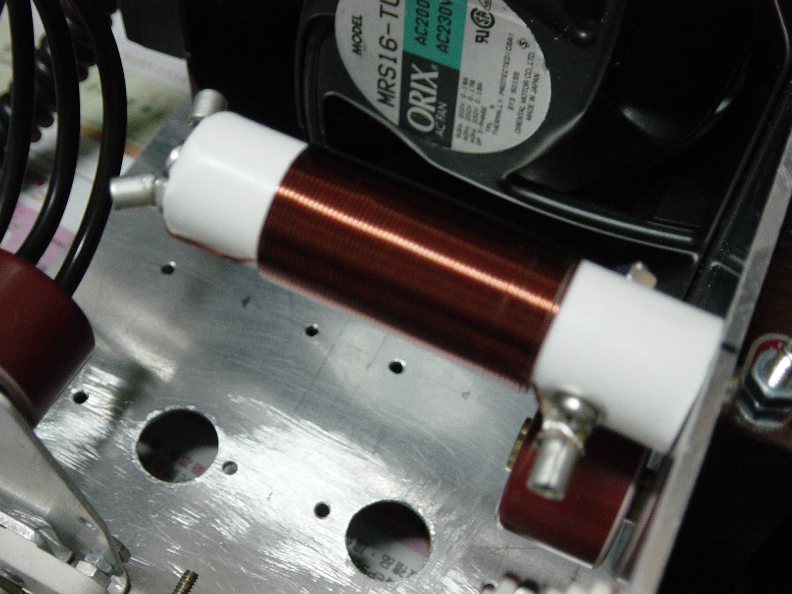
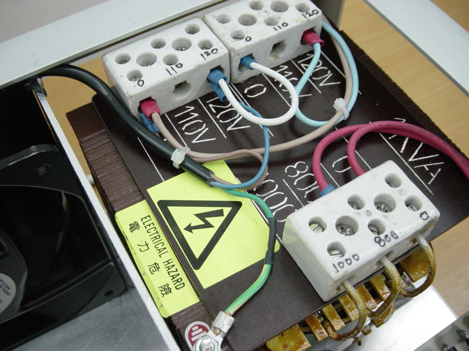
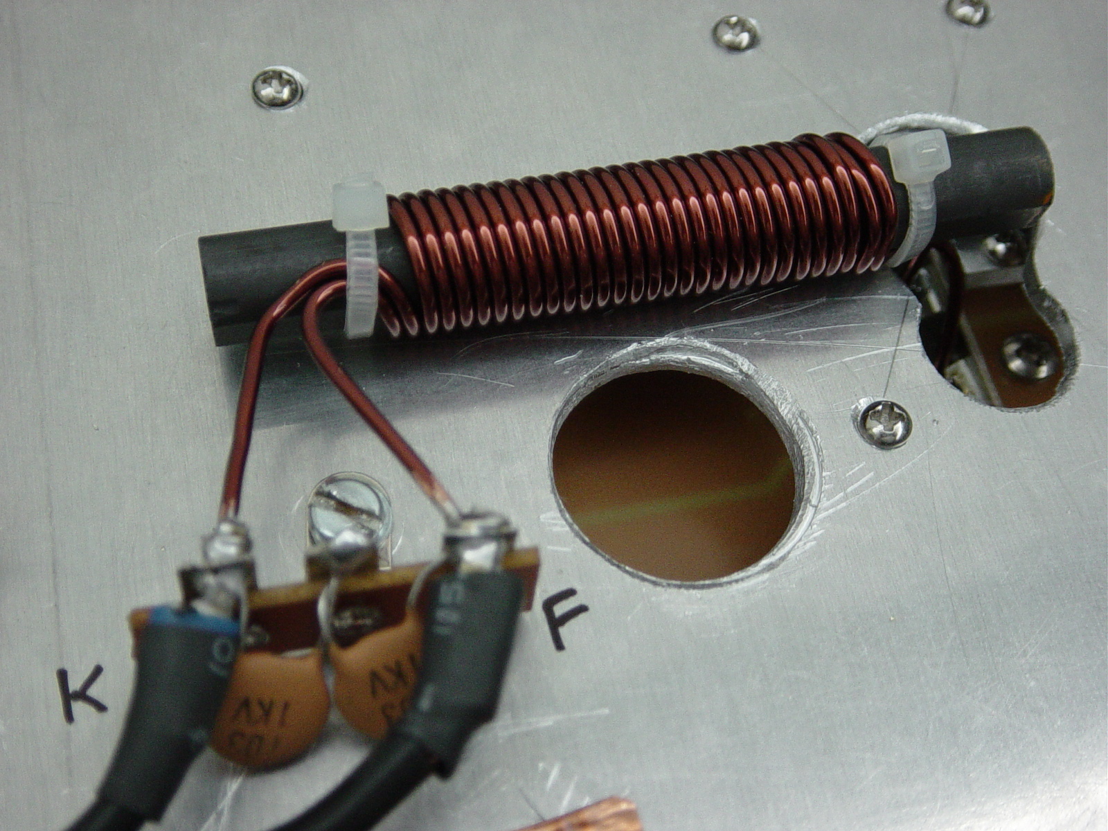
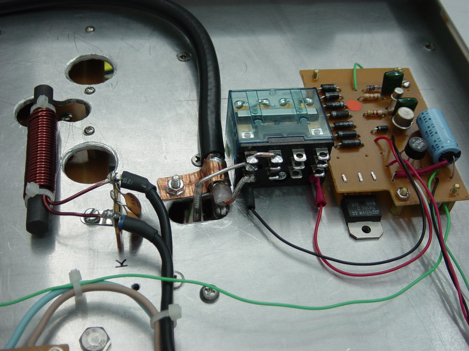
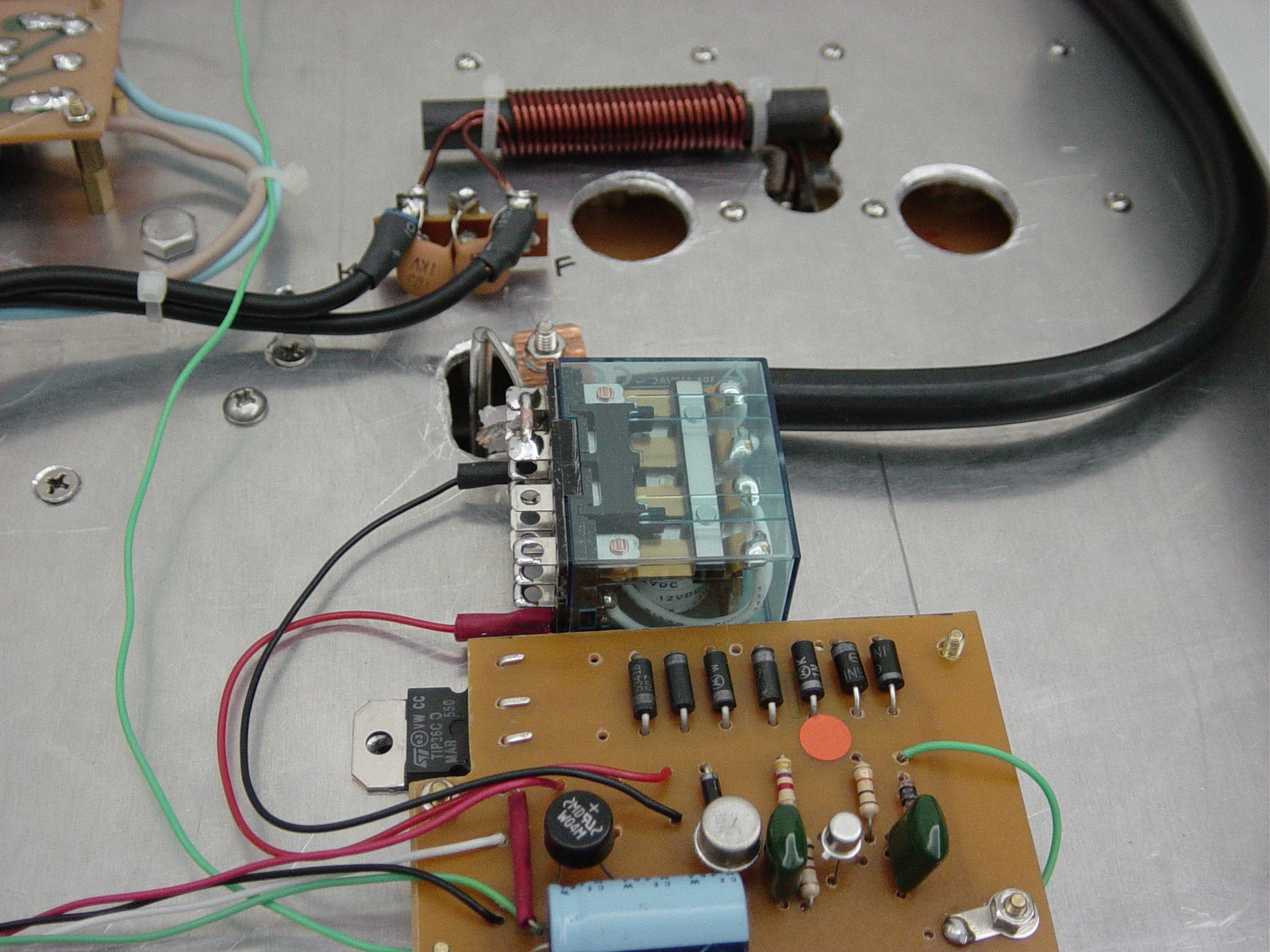
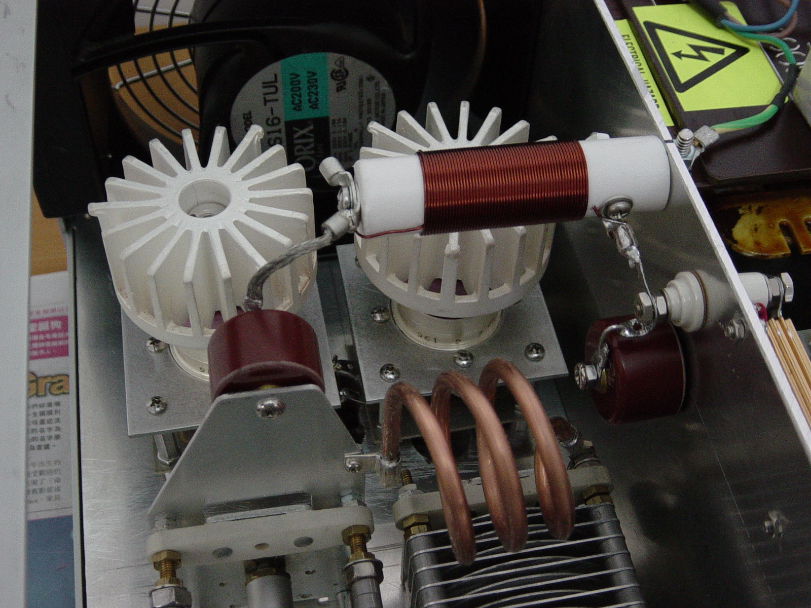
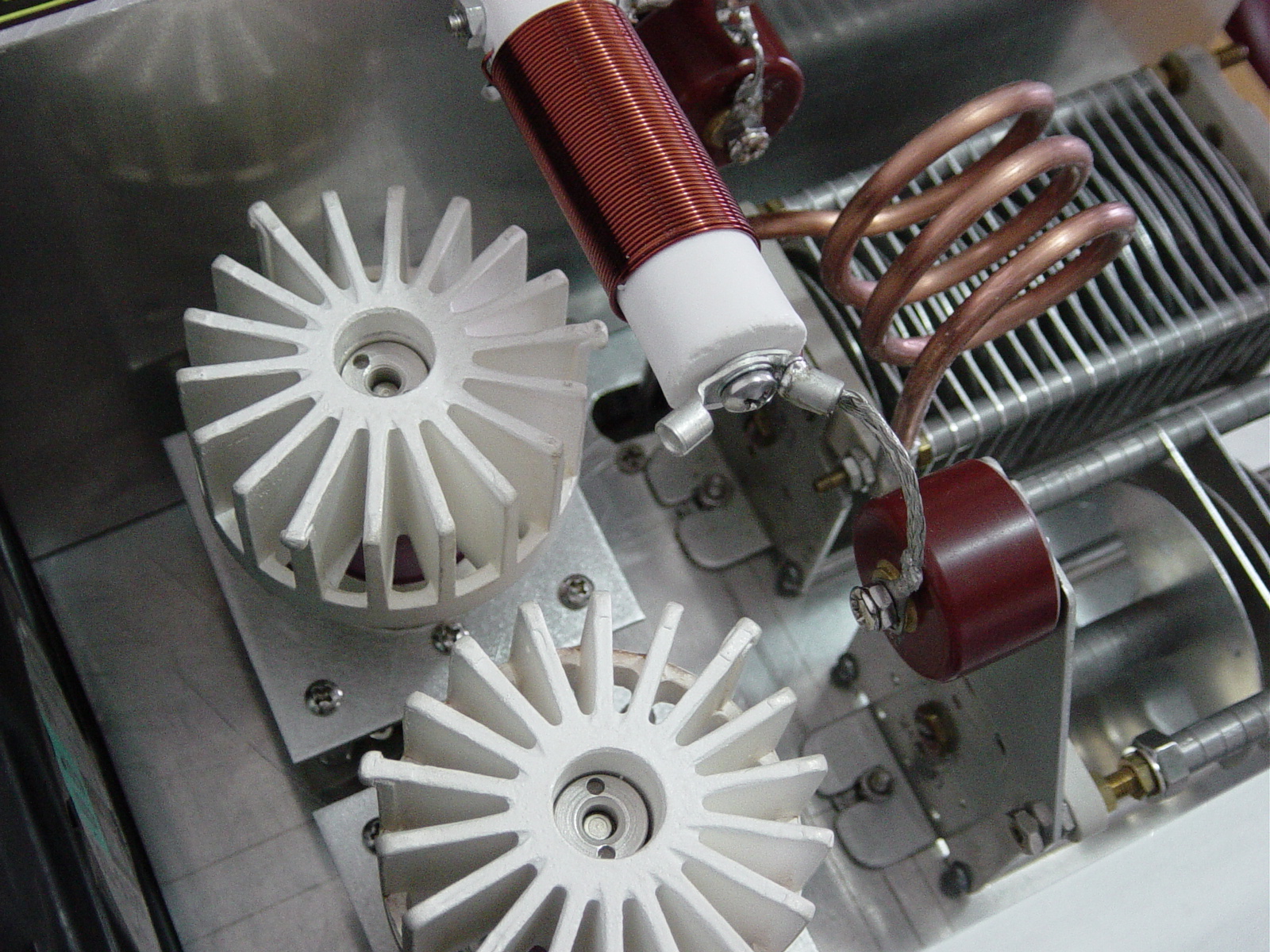
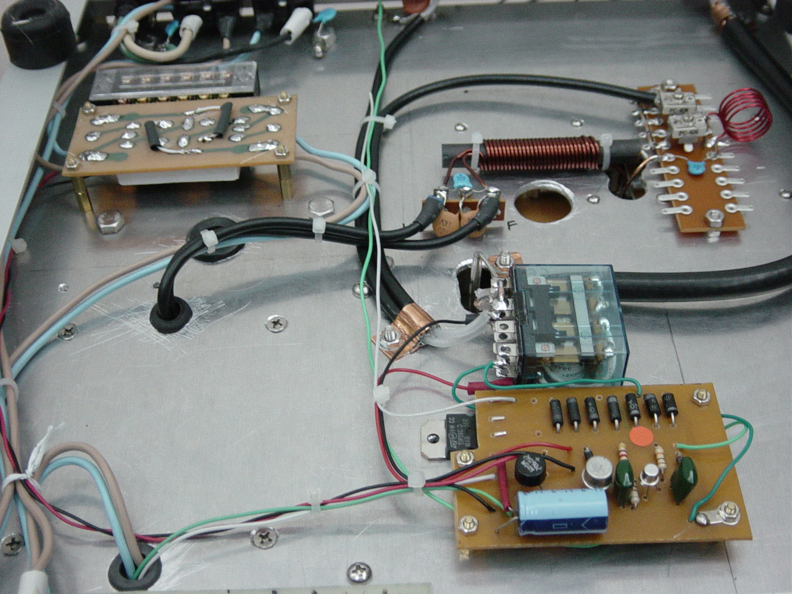
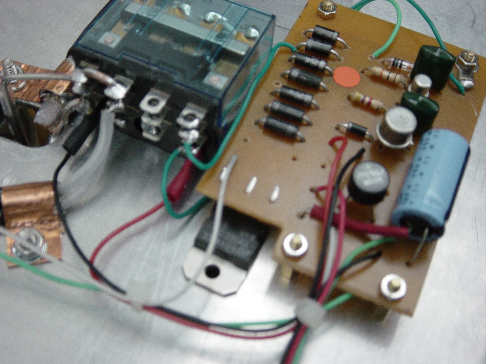
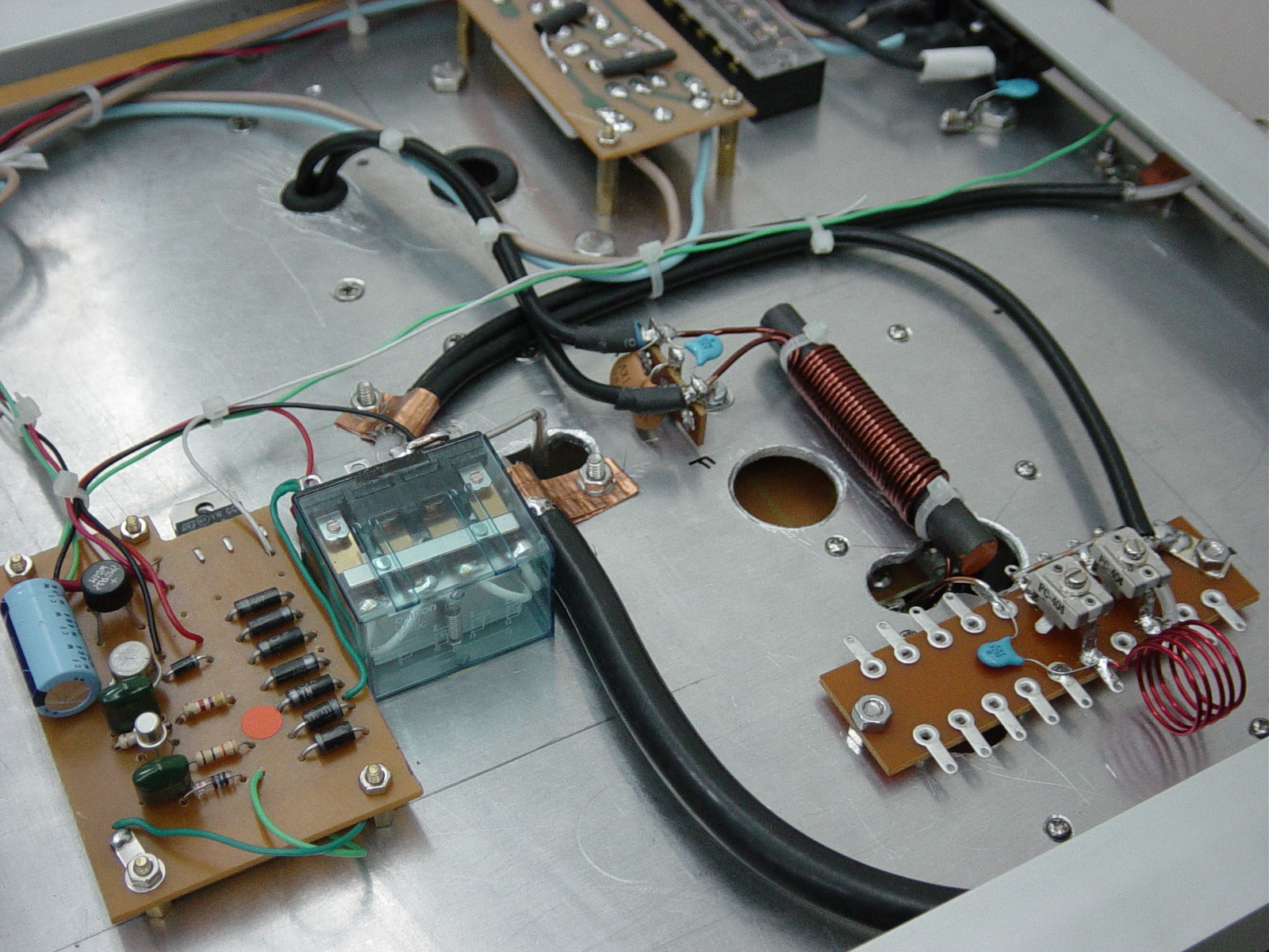
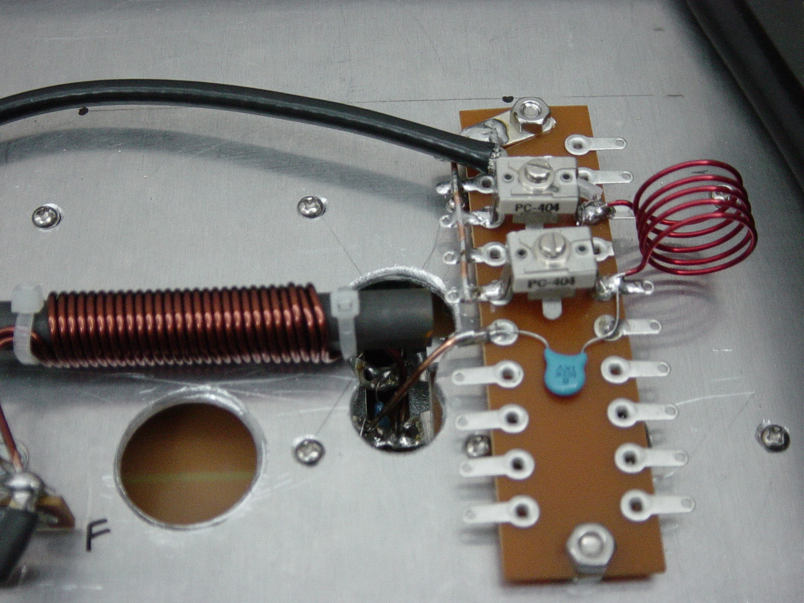
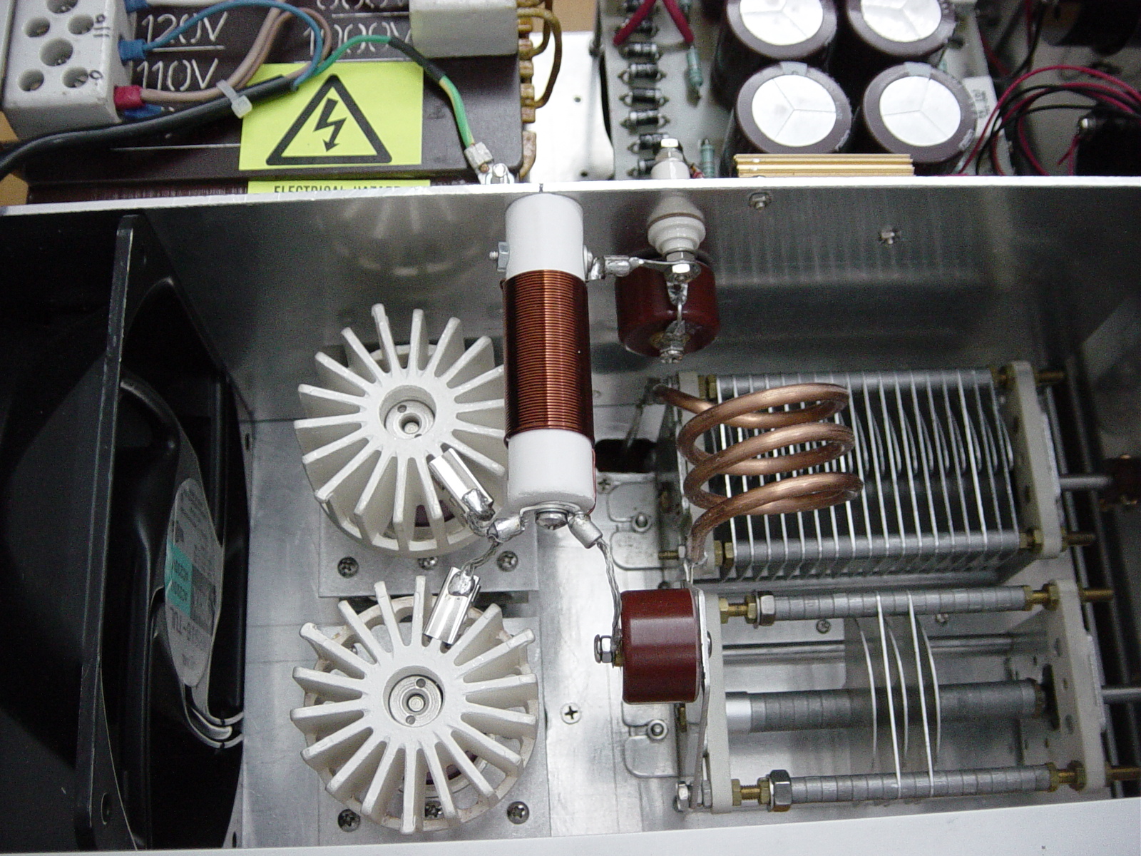
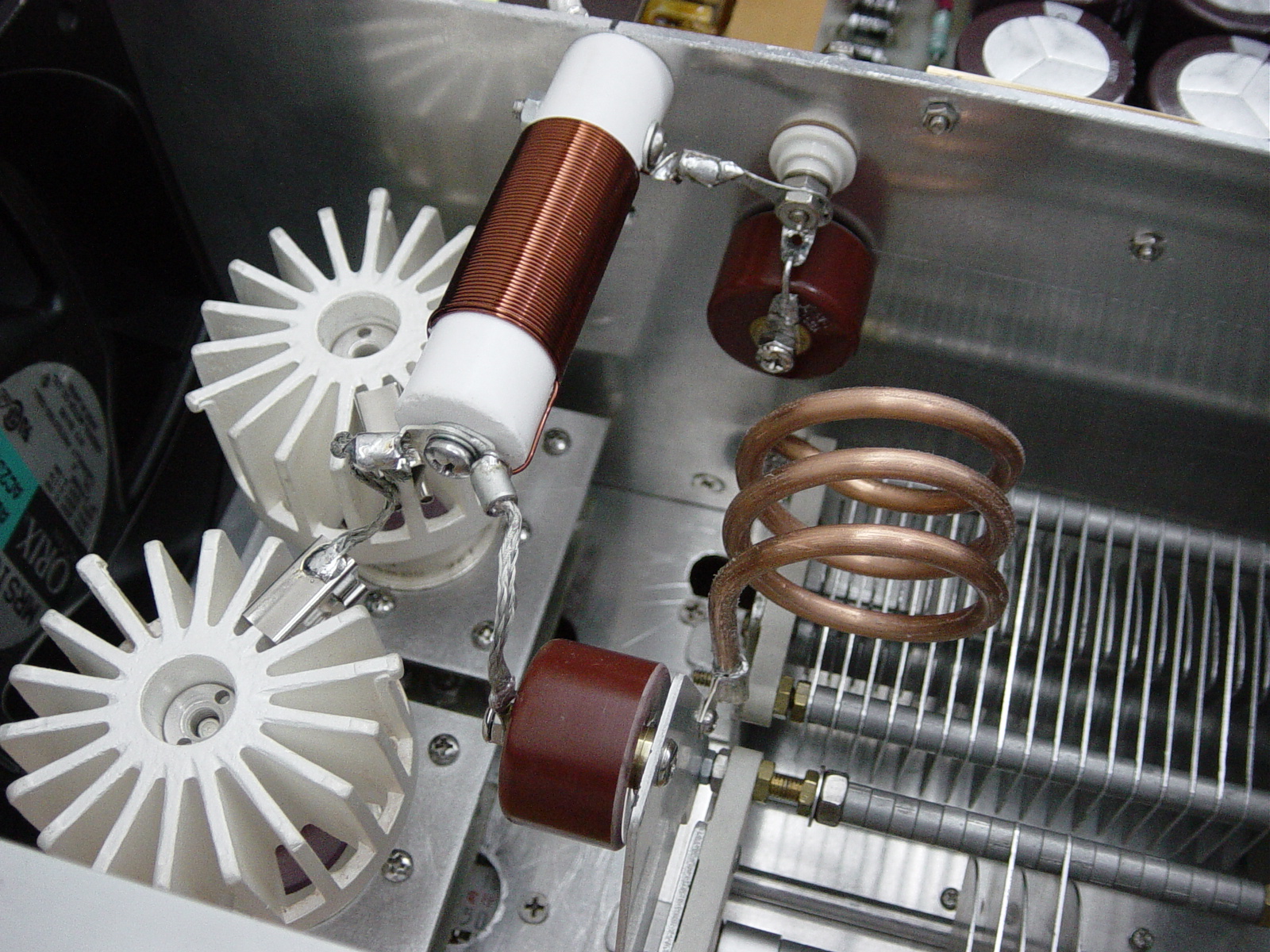
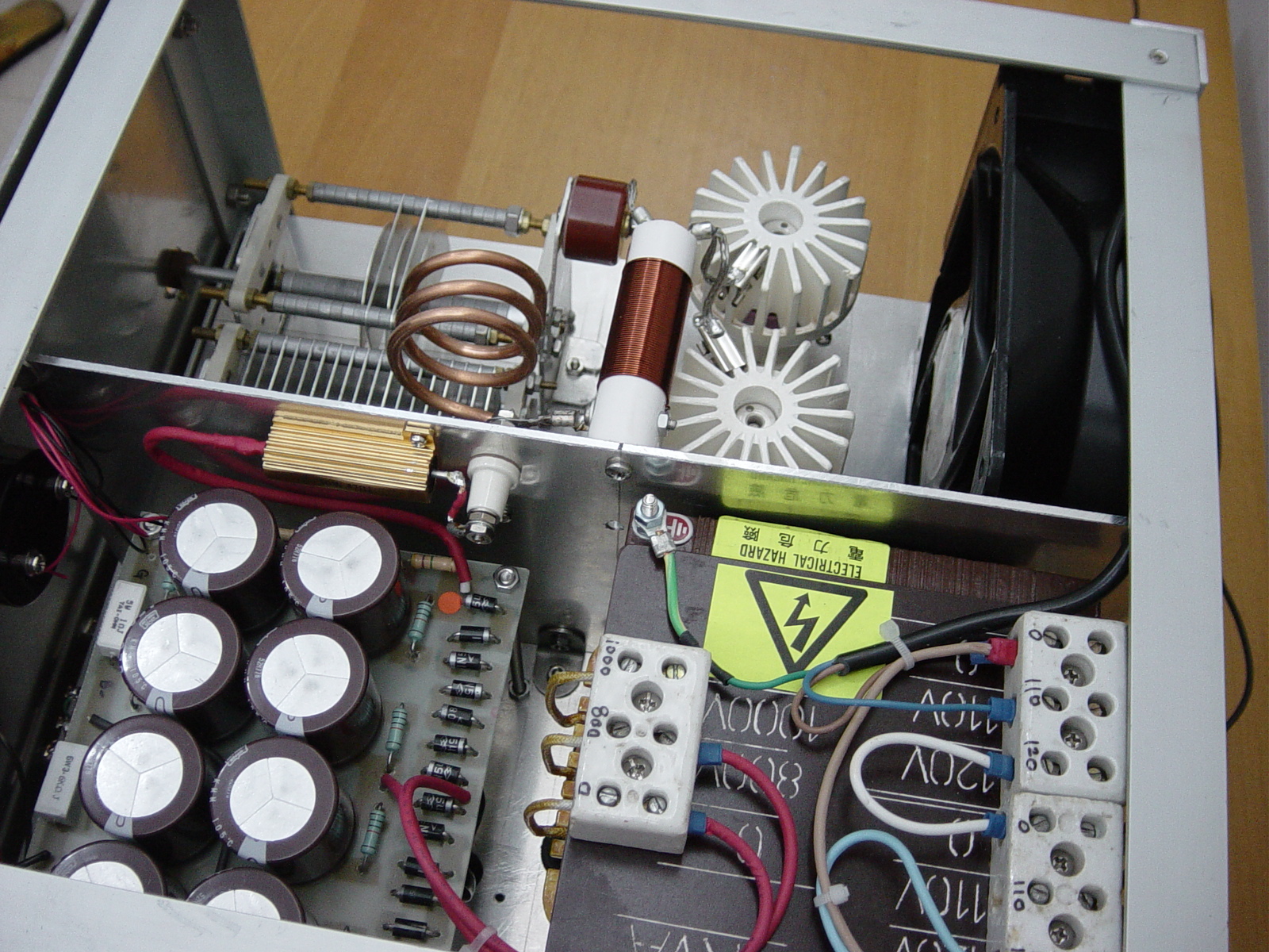
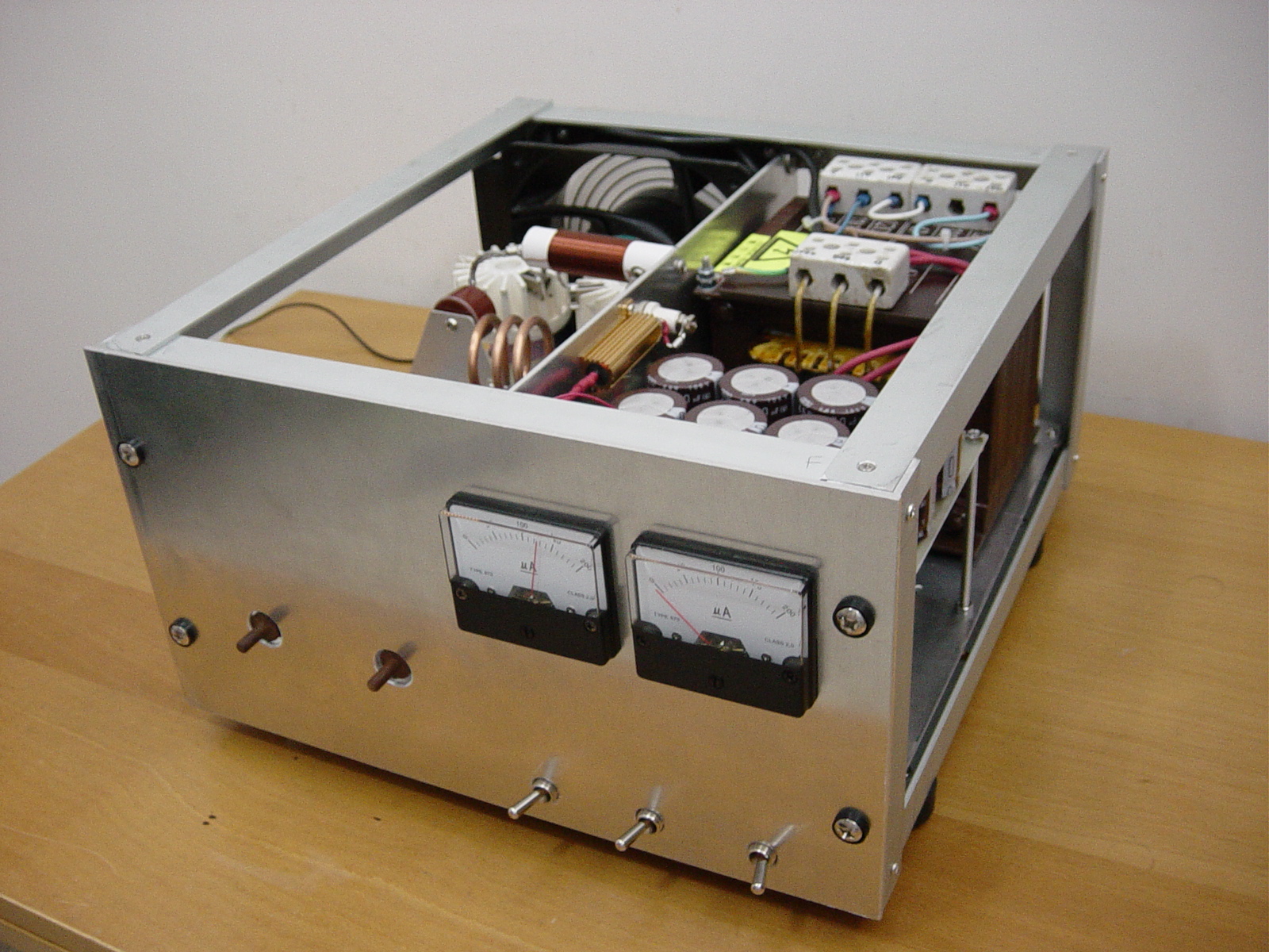
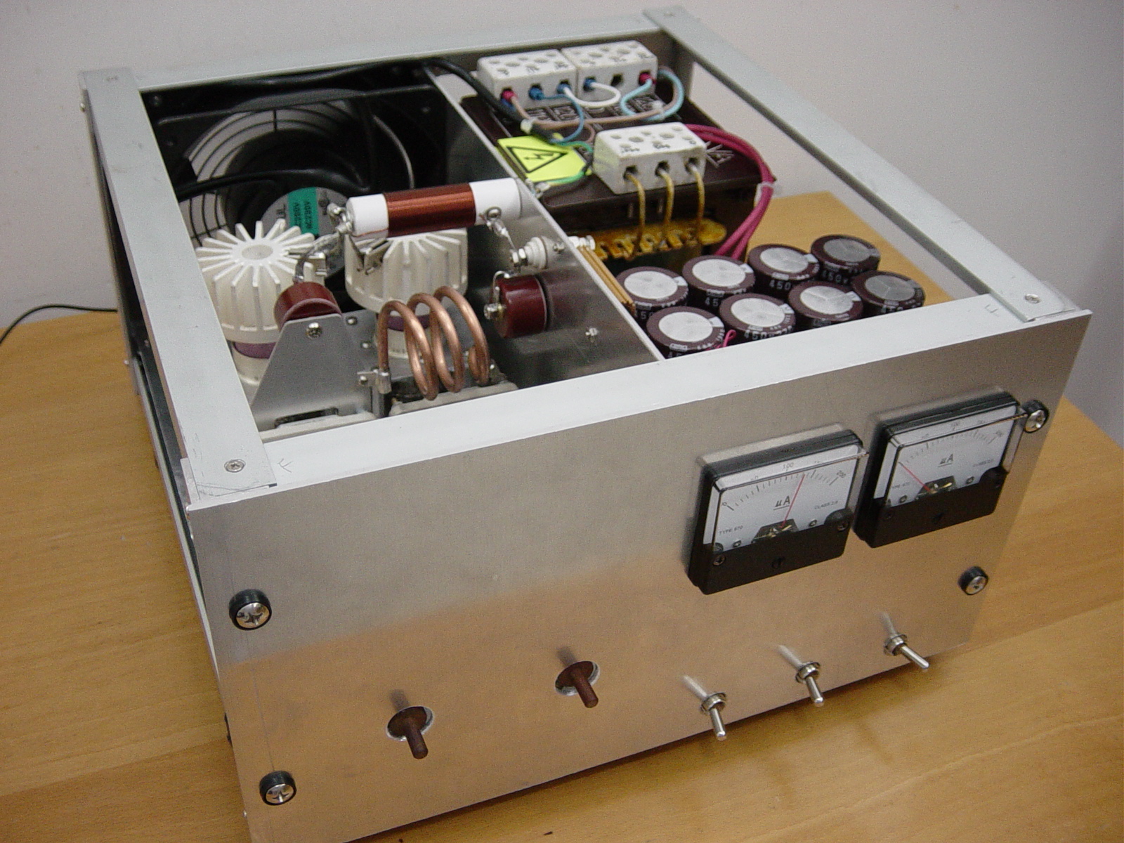
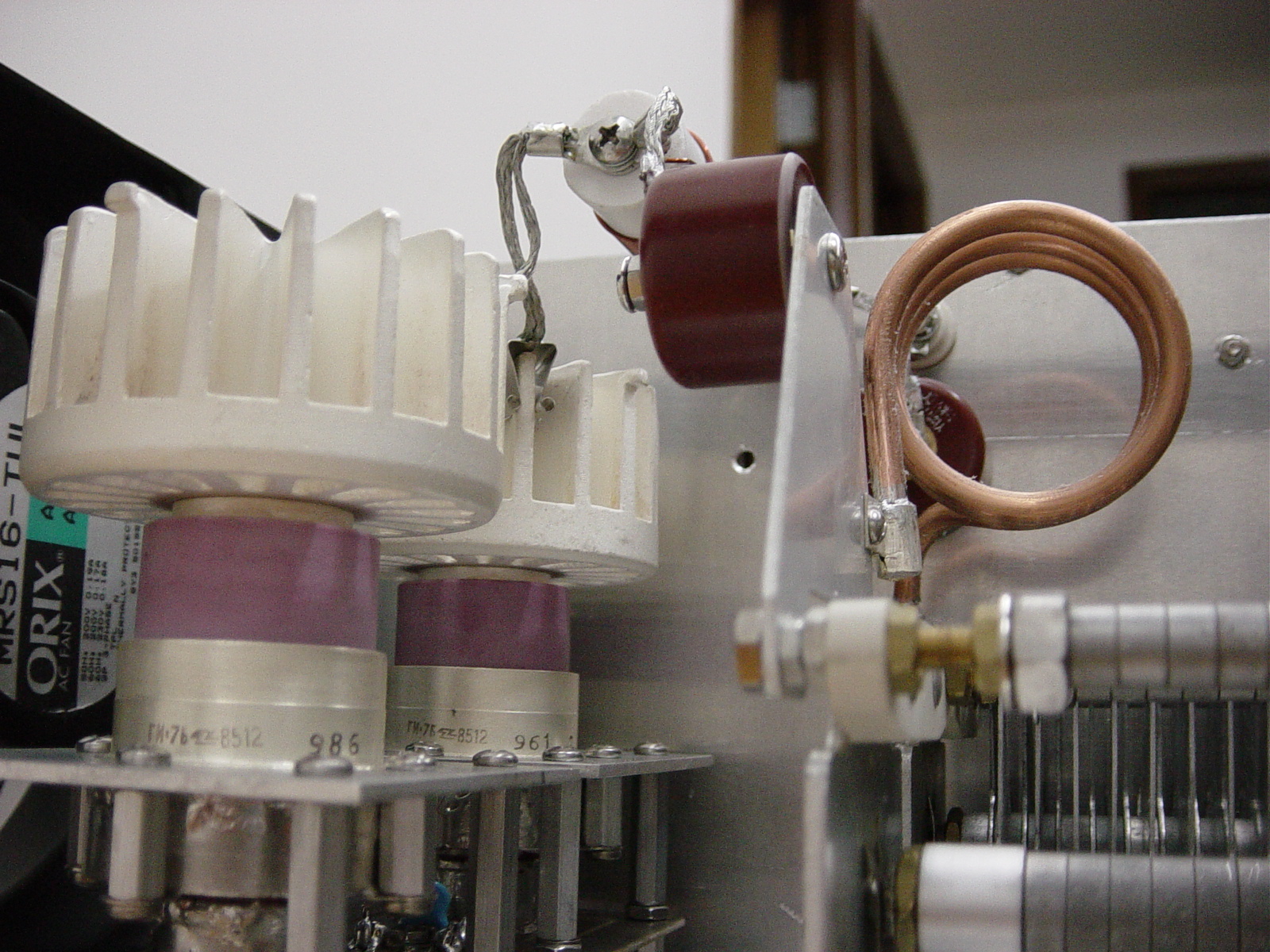
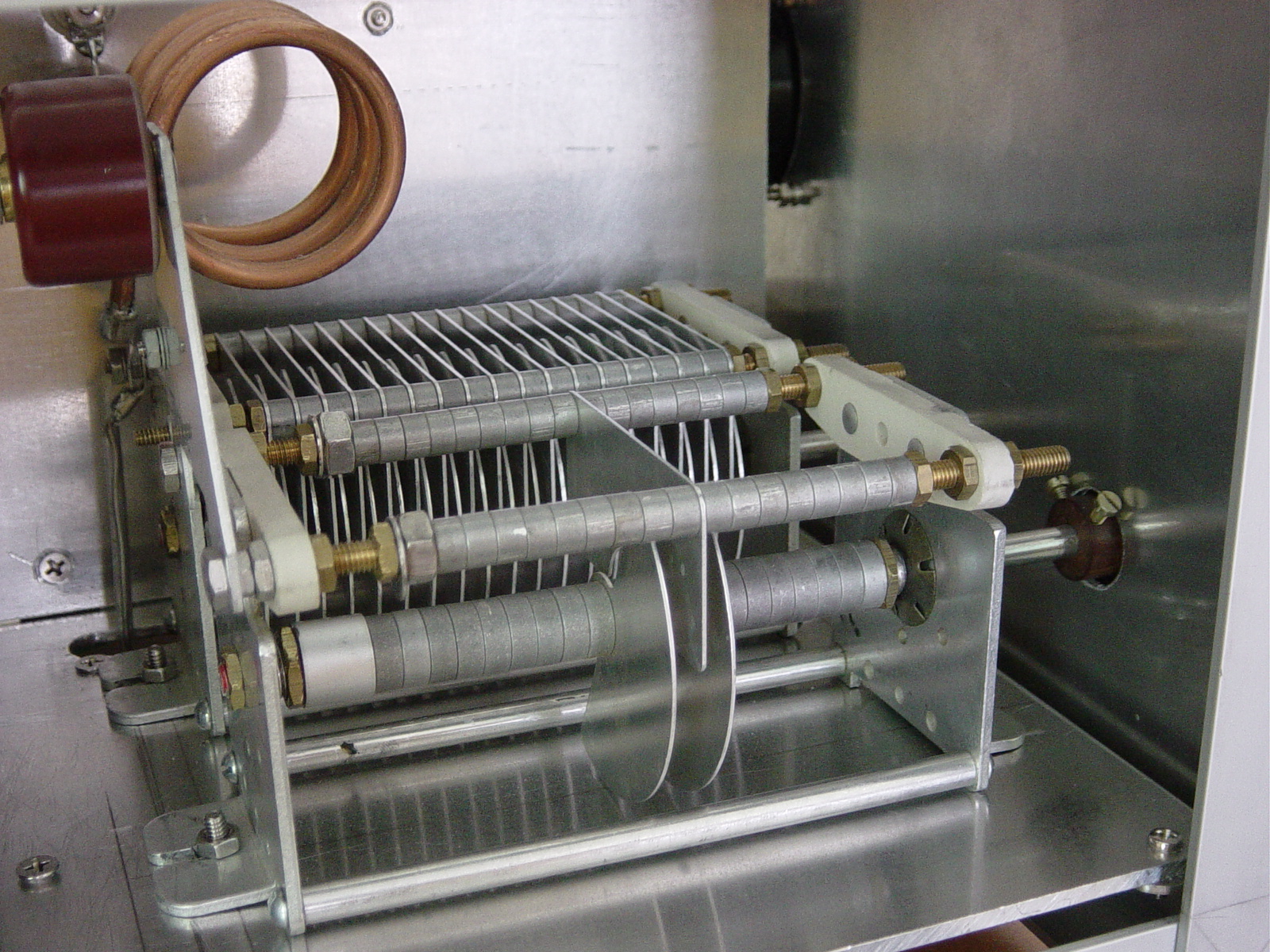
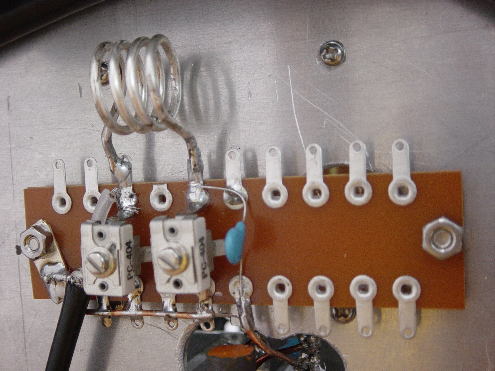
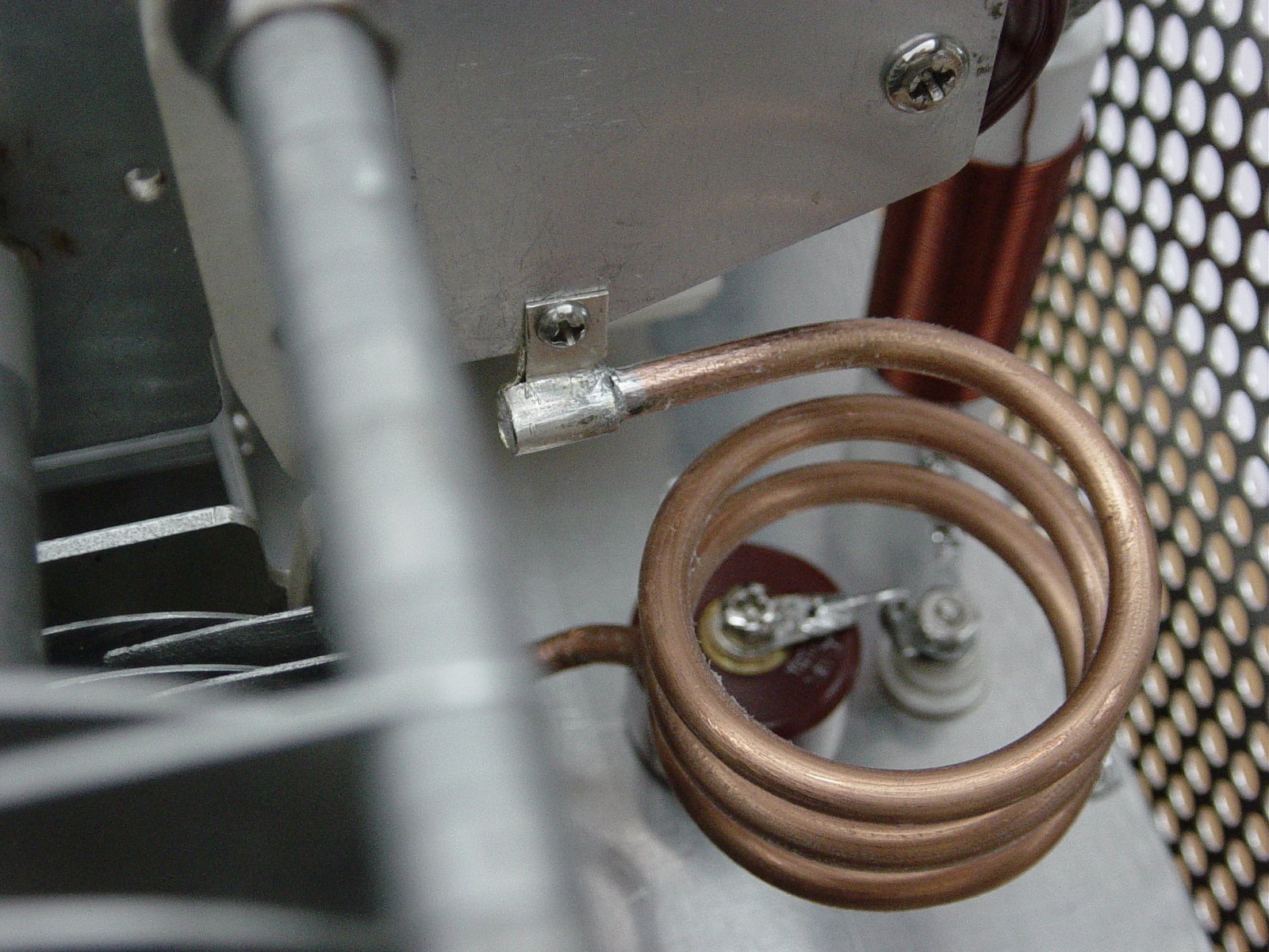
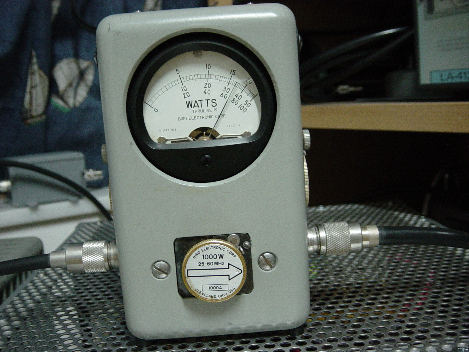
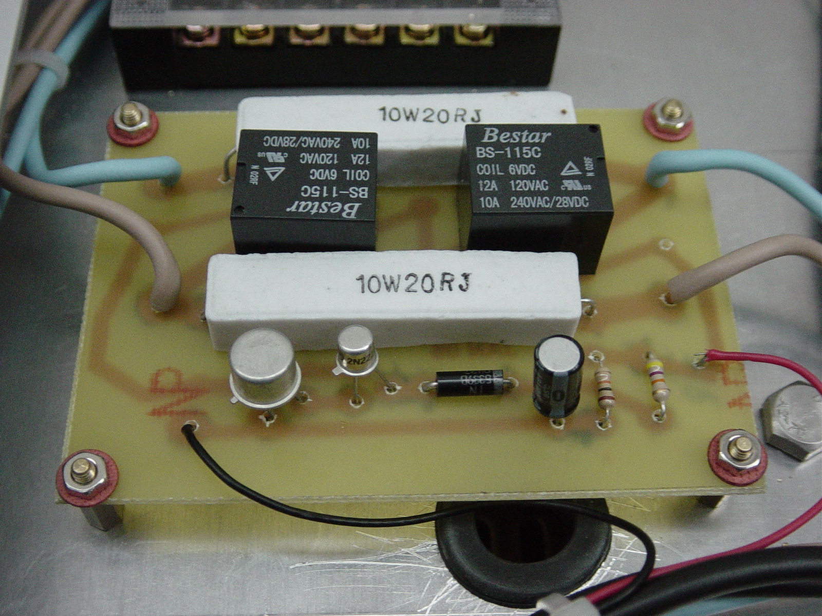
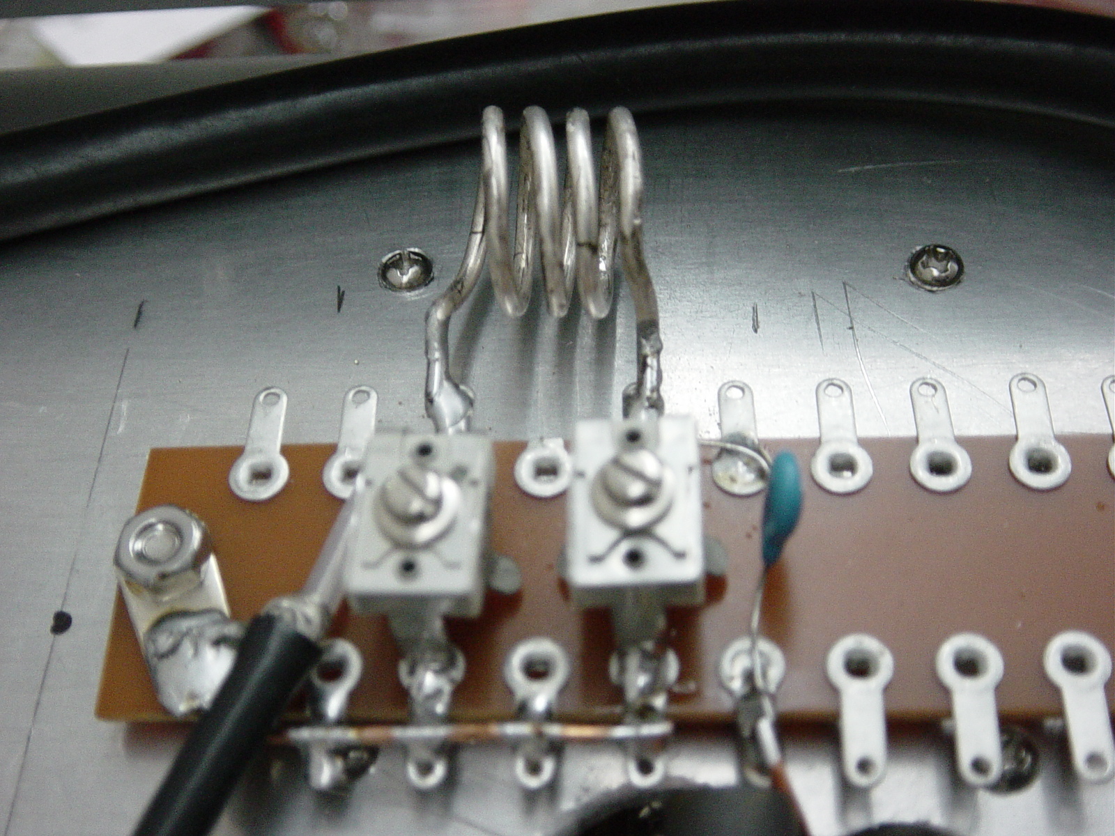
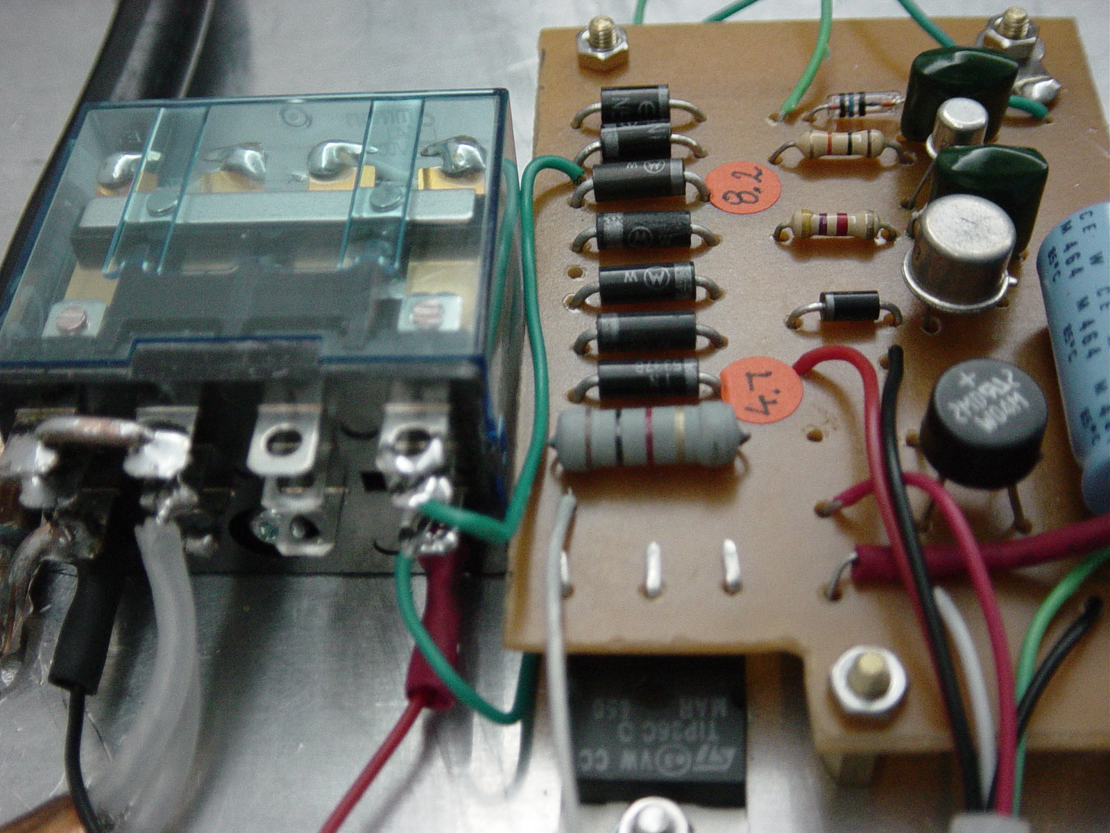
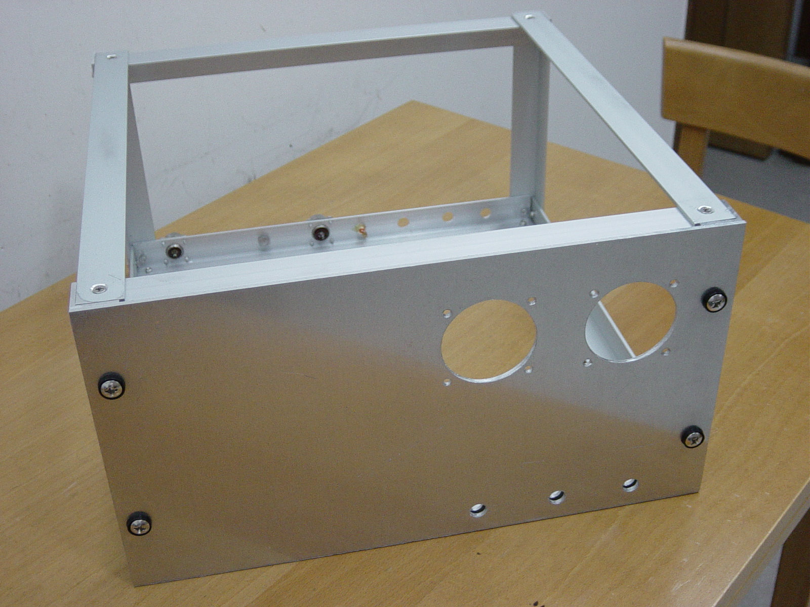
1) collect of parts -For the reason that commercial tube socket is not available and searching around the net and find it is available from W4ZT -Power transformer, still searching around if it is available to wind in local market. Otherwise, may need to find in Mainland. 2) Circuit - I refer to use YU1AW design. 20 ft - 1 inch aluminum angle and cut into small section for building the chassis of the GI7B amplifier. It cost $95 dollars including the entire cutting fee. The chassiss dimension will be at (360mm D x 350mm W x 200mm H ) Cut six pieces of aluminum sheets for the front panel and partition for the chassis. It cost of HK$215. I also locate one winding transformer company and ask for the quote for a 1000VA transformer at a reasonable cost. Size is approx. 6x6x6 and delivery time is one week. For the plate coil, it is quite difficult to get small diameter of copper tubing. It needs to buy at least a roll of several meter of quantity. So I give up this kind of material. Looking around and thinking of using surplus short length of hard line cable, center conductor is 5mm diameter. Wound 4 turn, inner diameter 40mm. Doorknob capacitor is 1000pf 15KV purchased from Mainland China. I have made the PCB Board Fabrication for High Voltage and Soft Start. This weekend, will go for the Software Key and Bias PCB. I also drill two big holes for the front panel meter High Voltage and Plate Current meter. Although it is a tough work, which took me an hour to complete, it looks very nice. I bought one 12V 10A contact rating Omron relay from Apliu Street, which is for the T/R switching. The plate choke is made from 50-turns, 22swg = 0.711 mm (purchased from UK), close wound on a 80mm length of 20mm PTFE rod(purchased from Apliu Street) AC 220V input to primary winding (240V) and secondary measured at 800V tapping is 730V. After rectifier and voltage doublers, measured at 2050V DC. It meets with the plate voltage of the GI7B. The soft key and bias board PCB is mounted at the bottom, nearby the T/R relay. Logan (VR2XRW) gave me a 10mm ferrite rod for the filament choke, it is in place all together with the input tune, consists of two Arco variable capacitors and 15mm dia. coil. All connections and perform initial test at the input SWR. At firs, the SWR is quite high with 1:3 , modified the coil to 4 turn 13 mm dia. with good result at 1:1.2. After that, connect plate voltage and measured the plate idle current at 80mA, which indicated it is correct. First RF test and found the tune variable capacitor totally meshed out, then I removed few plates and measured the capacitance is in between 4.5 to 10 pF. The tank coil also cut one Turn, now is 3 turns. The load capacitor is half-meshed, just fine. After that, test Starting with 5 W of drive from a TS-600, gave 85W on the output first time, which equal to about 12.3 db gain. Increasing the drive up to 10W brought 150W output, equal to 12.07 db gain. I stopped at this point because the 150W dummy load already very hot, will test later with a high power one. I also installed the top cover with ventilation holes. It is connected to a BIRD Dummy Load (Model 8401) and 43 Watt Meter and easy tune to approx. 700W output. End of the project. Look forward to hear you on the magic band. Finally, I made a new power-on delay relay circuit (soft-start) PCB yesterday. The zener diode which create a high turn on voltage for the Darlington connected transistor pair. The delay is approx. 3 seconds using 47K resistor and 100 uF capacitor. Longer delays can be obtained with a large capacitor. I use the modified SB-220 with full output for daily use. This DIY amplifier is the backup. I don't want to miss any new entity when band open. hi. Also, I learned a lot during the building process.
|

|
|
|
|
|
|

|
|
|

|

|
|
|
|
|
|
|
|

|
|
|
|
|

|
|
|

|
|
|
|
|
|