The FET-1 "Transceiver*" ?
By Glenn Yingling
W2UW
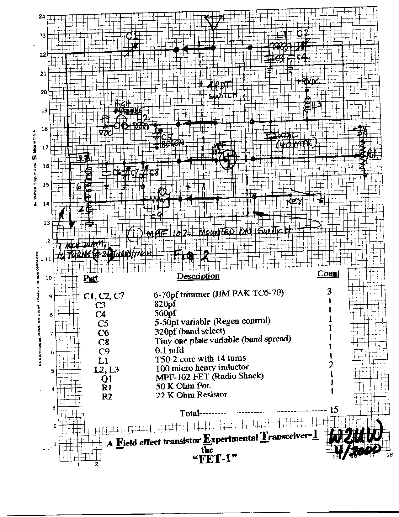
Here is the schematic for the little rig that I call the FET-1. Also
included are a few notes on building and tune-up.
I sent the full article to the 73 magazine and I am waiting for them to tell me that it is
being accepted for publication.
If you decide to build this beauty, please consider calling me to set up a schedule for a
rig to rig contact. I would
like to hear how it sounds and would like you to be the first one to make the FET-1 to
FET-1 contact ! Hi. So
far I have worked 17 states and 2 providences with my best DX being Eagle River Wisconsin
which works out
to be 36,250 miles per watt !

DETAILED ELECTRICAL CIRCUIT
-Fig. 2 shows the
electrical schematic of the FET- 1. Please note that the
(Radio Shack, 276-2062) is mounted directly on the 4
common switch terminals. It is used for both the
the FET transistor because it works
RECEIVER NOTES
-For the 40 meter band, tuning is set with the
following:
-The 320 pf cap gets you to the 7.0 MHz range.
-The 6-70 pf cap lets you home in on the frequency of interest- -in my
-The small variable cap (one plate) lets you tune around 7040 KHz as
-The 5-50 pf variable cap provides feedback to the oscillator for sensitivity
until the Regen is on the verge of oscillation. Any
-This circuit works good and the layout for 40 meters is not critical, but try
-You will hear a signal on both sides of “zero beat* allowing you to hear each signal
“twice” on
your dial, unlike your superheterodyne .
-The 9 component (including the transistor) Regen receiver will bring in
those received by your expensive receiver. But ,
-The downside of this story is that it is so sensitive that it can be easily
signal or a nearby station. ( I didn’t care, so I
control. Also, at
can get some degree of attenuation by putting a variable
supplied to the Regen.)
-With the limited frequency range that I wanted ( 7040+/- 15 KHz.), once
control, you don’t need to adjust it again.
TRANSMITTER NOTES
-Adjust the 50 K Pot and the (6-70 pf trimmer
for maximum output of the
Ohm resistor.
-The transmitter puts out approximately 20 milliwatts. Power is calculated
1 .- (Peak to Peak volts)/2 x 0.707 = volts rms
(PET- 1) 3 volts/2 x 0.707 = 1.06 vrms
2 .-(vrms squared)/50 ohms = Power in watts
(FET- 1) (1.06 x 1.06)/50 = 0.022 w = 22 mw
GENERAL NOTES
-The 100 micro henry rf chokes are somewhat non
critical. Try whatever
have that are greater thau 100 micro henrys. I
henry chokes that cost me a
-The 50 k ohm pot is also somewhat non critical. Try any pot up to 500 K
-When I run this rig, I use one “D” cell from a flashlight for power.
because I use a DC-to-DC converter to boost the
- I did not even put a ‘power on/off' switch on the FET- 1 ,
instead I use
power supply switch.
-1 did not put a sidetone monitor on the FET- 1. I just use the sidetone
There is plenty of space for later addition of a sidetone to the
desired in the future.
Glenn
Yingling W2UW
28 Lawrence Ave
Newark Valley, N.Y. 13811
* Note that the MPF-102 transistor (Radio Shack 276-2062) is mounted
directly on the 4 pole double throw
common switch terminals and is used for both the receiver and the transmitter sections.
(So, would this be considered
a transciever?)
Good Luck
Glen E. Yingland W2UW
Pob 62
Newark Valley, NY 13811-0062