My Yagi Antenna Project
It's been a long time coming, as it does when you have to go out and
scrounge, buy and make bits and pieces for the project. The idea
started when I had the opportunity to get a mast for a good price.
The Mast
The triangular steel mast is in 2 metre sections. Two sections
were damaged, and I repaired one and sacrificed one to set into the
concrete base as a mounting point for the mast. That left me
seven sctions to make a 14 metre mast..
The concrete block is about 600mm square and almost
as deep, however intruding into the hole from two corners were the ends
of large sheet rock just below the surface. The concrete
wraps around and under the rocks, making a very solid foundation.
The mast came with a "carriage" that runs up and down the side of the
mast using four grooved wheels. I refurbished and reinforced it
to carry the large antenna, rotator and bearing.
The bearing is a stub axle and housing (normally used for making tailer
axles) - this would provide me with all the thrust (downward) and
lateral support for the four metres of steel pipe carrying the yagi and
a 2m-70cm vertical on top.
The Antenna
I looked around for a long time for a suitable antenna - I narrowly
missed out on a TH6, and I think I was lucky - its a huge bugger.
I eventually came across a Chirnside CA-35DX 5 element job.
This antenna is 3 elements on 15 and 20 metres, and 4 elements on
10 metres,  It's
still fairly big with a boom length of 5.7 metres. I had to drive about
130 km out into the wheatbelt to pick it up, but it was a nice drive.
The fellow I bought it from runs a camera museum in Cunderdin.
It's truly worth a look.
It's
still fairly big with a boom length of 5.7 metres. I had to drive about
130 km out into the wheatbelt to pick it up, but it was a nice drive.
The fellow I bought it from runs a camera museum in Cunderdin.
It's truly worth a look.
The antenna needed some refurbishment, and all joints were
disassembled, cleaned and reassembled with elecrical jointing grease
for corrosion protection. The nylon bushes supporting the driven
element were distorted and cracked, and these were repaired with expoxy
glue, a "rebore" with a spade bit and splinting with some PVC water
pipe and stainless steel hose clamps. The traps on the reflector
were a bit wobbly, so they were pulled apart and refurbished, again
with Epoxy Resin used to rebuild some of the plastic bits.
The home-made balun was destroyed by water ingress, so I made a new one
mounted in a plastic waterproof casing. I since abandoned the
wire wound balun and made a coaxial choke (about 10 turns of coax).
The Rotator
I purchased a second hand Daiwa D-R7500R rotator which appears to be in
good condition. I stripped it down and cleaned and lubricated it.
It now sports a nice fresh coat of forest green enamel.
The small rectangular hard pastic cover for the cable connections had
one corner broken out of it, so out with the expoxy, made formwork out
of insulation tape, and recast the corner, filed and drilled it then
painted it black. You'd have to look closely to see the repair.
About 9 months after installing the antenna and rotator,
the direction indicater on the controller became erratic, and after
puttingup with it for a while, down came the antenna, off with the
rotator, and pulled out the potentiometer. Luckily it was a good
quality wire wound one, so I was able to dismantle it, clean it
out, put a new sheen on the contact surfaces with some fine abrasive
paper, give it a final clean out with one of those aerosol contact
cleaners and reassemble it. A tip for those of you brave enough to
tackle a rotator: Before you reassemble the outer ring gear, set
the pot to give a balanced reading (eg equal OHMS between the centre
contact (wiper) and eah of the two outer contacts. You can then
put on the outer ring gear, making it point to the postion 180 degrees
from the STOP position. I checked the readings again after
assembly, and they were still correct. When I attached the
controller cables and turned on the controller, I moved the pointer
manually to "NORTH" (I have the stop position at "SOUTH"). It
works perfectly now.
The problem now was how to mount the rotator and bearing assembly
to the carriage. I eventually got it right, by using mechanic's
tools as a drive train - a socket wrench, universal joint and
extension bar connect the rotating assembly to the rotator.


As you can see in the picture, I had to reinforce the carriage to stop
it flexing with a load waving about above it. That's the bits you see
with fresh cold galvanising paint. Today is 19 December 2007
- everything is almost set to go. All I have to do now is
get the antenna about 2 metres off the ground and tune it, then
organise a few freinds and a cherry picker to assemble the mast.
Hopefully it will happen soon, and I'll be on air with it.
Saturday 29th December 2007 - Mast Building Day (= Erection Day?)
I hired a cherry picker and with the help of Tony VK6HAM we put up the
mast and antenna. It was hot work out in the sun
and we had to take frequent breaks in the shade with cold drinks
(soft!). The cherry picker didnt go as high as I expected so we
only put up 6 sections, giving the yagi a height of just under 13
metres and the 2m/70cm antenna when attached to the top of the pole
will be at about 15 metres.
The rotator played up and I'll have to get it back in the shack
and find out what's happening. Nevertheless we put the antenna up
into place with a rope tied to one end so we can rotate and secure
the beam. Sunday I will tweak up the tuning of the beam
as it has altered "up there". Update: After
consulting with Peter VK6AAL I sat down and worked out that I had not
replaced the cog on the potentiometer in the rotor in the right
position. After working out where its stop position should be, I
reassembled it and it worked perfectly.
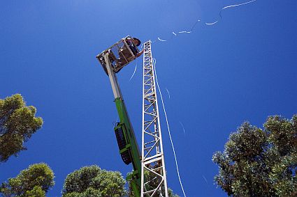

Me in the Cherry Picker
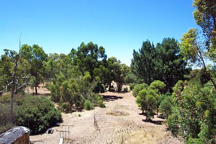
Looking North from near top of mast . The 80 loop, which isnt visible
Antenna pointing North
in the pic, is above the clearing.

The view down
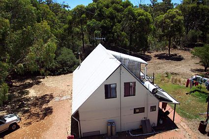
View over the house
Tweaking (cont'd)
I checked the resonant points on each band on 4th January 08. These are at 28.6 MHz, 21.2 MHz and 14.224 MHz.
The impedance was a little high on 10m at 71 Ohms and one day
I'll play a bit and try to improve it. As it involves cranking
the assembly up and down a few times I think it might be some time
before I do it.
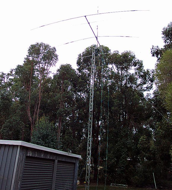
Completion Photos
I was recently reminded that I haven't posted pics of the finished job. Here are some.
Update 9th March 2010
I
discovered a week or so ago that I had the dedicated 10m elements mixed
up, basically turning the 10 metre section of the antenna into a
3 element beam pointing backwards. I discovered this when a local
ham was working 10m shortpath into Europe one afternoon, and I was
hearing the station longpath. Sort of an "AHA!" moment as to why
10m was never working well on this antenna. Anyway, all fixed
this morning - swapped the two elements over, did some tweaks on the
rotator drive train and its back in the air.
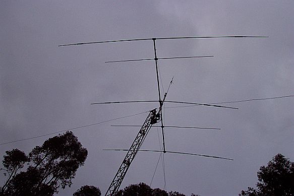
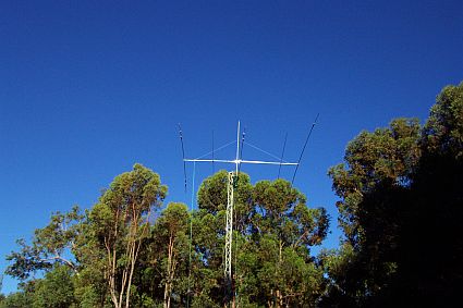
The Chirnside Antenna shown against a nice dark sky.
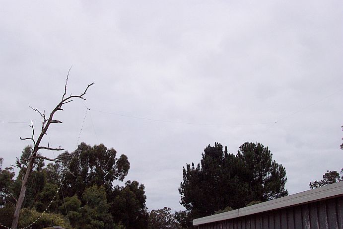
This is the 80 metre loop. You can see the feedline going up from bottom left.
You can't see the wire clearly, however the feedline is in one corner, and the two taller trees in the background
support two corners. The 4th corner is supported by a large Jarrah tree off the picture to the right.