Measurement of output balance. |
Introduction
Just when we thought we were all through with testing Z match tuners sornething else turns up. Recently, Rob Gurr VK5RG brought my attention to an article in the Winter 1995 issue of Communications Quarterly by Charles A Lofgren W6JJZ, titled "Beyond the Z Match".
In the article, the writer expresses concern that the assumed balanced output circuits of many of our antenna tuners actually introduce unbalanced currents on balanced lines. He points out that this becomes particularly serious when the load impedances become very high, such as when tuned feeders of certain critical lengths are used. The unbalance produces high radiation from the feedline, possibly encouraging RFI problems, unwanted RF in the shack and changes to the radiation pattern of the antenna.
One of the features we have promulgated for the Z match is that it is suitable for both unbalanced and balanced output and the point of my attention is that W6JJK targets the Z match as one of the tuners which introduce the unbalance mentioned .
Of all the test results I have previously submitted for various Z match models, none has included tests to assess output balance. Hence the question now arises of how good, or how bad, is the balance of the Z match output circuit and that is the subject of this article. In the following paragraphs I discuss tests to determine the degree of balance, the results obtained and an idea to improve the balance.
Measurement of Balance
| W6JJK describes a method of measurement to determine output circuit balance for a given load resistance. As shown in Figure 1, a resistor of half the load resistance value is connected from each balanced output leg to ground. RF power is fed into the tuner which is set up for a correct match into the resistance load. The voltage is measured across each leg to ground using a high impedance probe. The ratio between the two readings is a measure of the degree of balance. |
|
I used the above method to measure the balance of a single coil Z match. We have described several versions of these in Amateur Radio, but the one used has the coil windings spiralled through the, drilled perspex sheet and designed to operate over the 3.5 to 28 MHz range. I point this out because I suspect that this air spaced version would measure better than the version wound on coil formers. I used half watt terminating resistors and reduced the transmitter power to a very low value so that the resistors did not bum up. I have a 0.5 watt FSD scale on my SWR meter which enables me to monitor this. To measure the voltages across the resistors I used a high impedance RF probe with a VTVM.
Results
Measurements were carried out for loads of 200, 660, 1120 and 2000 ohms using resistors of 100, 330, 560 and 1000 ohms respectively. Frequencies of measurement were 3.5, 7, 14 and 21 MHz. The probe specification is quoted as 2.5 pF with several kilohms resistance (depending on frequency).
This would seem adequate for the test, but I found it did tend to alter the loading a little at 21 MHz. I gave away the idea of recording measurements at 28 MHz as I felt the figures 1 obtained were too much affected by the probe. The results obtained are recorded in Table 1. The figures are given as the ratio of the lowest leg voltage to the highest leg voltage expressed as a percentage.
| Load Resistance Ohms | 200 | 660 | 1120 | 2000 |
| 3.5 MHz | 94 | 98 | 91 | 92 |
| 7MHz | 97 | 93 | 84 | 74 |
| 14 MHz | 95 | 85 | 83 | 50 |
| 21 MHz | 88 | 78 | 61 | 42 |
Just what figure of balance is to be considered satisfactory is probably open to debate. For the purposes of definition I will nominate figures above 90% as being quite good and above 80% as being tolerable. Applying these rules we find that there is a good balance at 3.5 MHz for load resistances up to at least 2000 ohms, and a good or acceptable balance at 7 to 21 MHz for load resistances up to around 500 ohms. At higher resistances for these frequencies (and in particular at 14 and 21 MHz), the balance is not so good.
Improving the Balance
The main theme of the W6JJZ article is the introduction of a circuit, more complicated than the Z Match, specifically designed to improve theoutput balance. He has called this the IBZ Coupler. In his coupler he uses a tuned coil arrangement, which covers two tuning ranges as in the Single Coil Z Match, but the tuned circuit is balanced by a split coil and a four gang tuning capacitor instead of a two gang. The coil assembly has a primary and secondary winding, as in the Single Coil Z match, but the secondary is tuned, whereas the Z Match tunes the primary. Taps on the secondary are also switched to select different load impedance ranges.
Unfortunately, the W6JJZ design gets away from the simple concept of our Amateur Radio Single Coil Z Match with only a single coil assembly and no switches (refer Amateur Radio. April 1993). The four gang tuning capacitor is also a further complication. Two gang capacitors are difficult enough to find as it is. Fortunately, there is a simple way to improve the Z match output balance without circuit re-arrangement.
Recalling the results of my tests, output balance seems to be only of concern if you are using balanced lines which reflect a resistance component of above 500 ohms and the operating frequency is 7 MHz or above. If your operation does not include all those conditions, then there is no problem and there-is no need for anything to be done. Even at 7 MHz the unbalance figures are not really that intolerable.
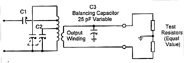
On the other hand, if you must operate high impedance balanced lines in the upper HF bands, you might consider a small modification to the Z Match which I will describe. However, before doing so, let's examine why the unbalance occurs. The unbalanced signal component is coupled longitudinally into the output secondary winding of the Z match coil via capacitance between the primary and secondary windings. Its voltage on one leg of the output winding relative to earth is different from the other leg because, generally, the capacitance of one leg to earth will differ from the other. A voltage balance can be achieved by altering the relative values of the two capacitances to earth. To do this, a small variable capacitor of around 20 to 25 pF is connected between earth and the output leg furthest from the cold, or earthy end, of the primary winding (refer figure 2).
I found that in my single coil Z match, the balancing capacitance added needed to be around 15 to 20 pF, its value being a little different for the different bands. To set the variable capacitor, the test set up with the two terminating resistors is again used and the capacitor is adjusted for equal voltage at the two output legs to earth. This could be set for balance on the band where it is most needed with, perhaps, some out-of-balance error on other bands. |
|
The same unbalance test can also be carried out to cheek the coupled system using the actual balanced antenna instead of the terminating resistors and measuring the RF voltage at each leg to earth as before. This can give some surprises when you find out the balanced antenna line isn't quite balanced at all. When the line is connected to the tuner output, the line imbalance is either added to the tuner unbalance, or corrective of it, depending on which way around the line legs are connected. The balancing capacitor can be used to balance the resultant of the two together.
Adding capacitance at one leg might make the voltage unbalance worse. If this is the case, the balancing capacitor must be connected to the other leg. Incidentally, to determine whether any unbalance is in the antenna line itself, it is only a matter of observing the two leg voltages when the line connections are reversed. If the highest and lowest readings interchange, then there is unbalance in the line. Of course one should not get too pedantic about this as a small imbalance might have little effect on the overall performance of the antenna system.
More Tests on the Two Coil Unit
To get another assessment of output balance in the Z Match, I repeated the tests on the "Compact Coil" or "Rononymous" version of the two coil Z Match. The following is a summary of the results. Good balance was achieved at 3.5 MHz using coil A for output loads up to 1000 ohms, but not at 2000 ohms. A good balance was also achieved at 7 MHz with coil A up to 660 ohms. Coil B gave surprisingly good balance at 14 MHz over the whole tested load range of 200 to 2000 ohms. By contrast, at 21 MHz with coil B, poor balance was experienced over the whole of the load range.
|
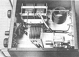
The original Compact Coil version of the Two Coil Z Match (as shown) was made up by an Australian Radio Amateur for QRP use. It was published in the December 1990 issue of"Amateur Radio" through the Two Rons' Random Radiators Column. Because the Amateur liked to remain anonymous, they called it the Rononymous Z Match. |
The results are somewhat more random than obtained using the single coil Z Match, but the general trend is the same with balance deteriorating at the higher frequencies and when the load resistance is very high.
Summary
One of the features of the Z Match tuner is that it is suitable for both unbalanced and balanced loads. Just how good a balance it provides on balanced loads has been questioned. Tests described indicate that the balance is quite good at the low end of the HF band, such as at 3.5 MHz and to a lesser extent, at 7 MHz. At 14 MHz the balance seems reasonably good, provided the load resistance is not too high. At 21 MHz the balance for low load resistance appears tolerable for the Single Coil Z Match but not so good for the Compact Two Coil Z Match. No tests were carried out at 28 MHz.
Correction of the output circuit unbalance, using a small variable capacitor across one leg of the output circuit, has been discussed.
For most applications using the Z match tuner, one can forget about output balance. Our only concern is when we feed high impedance balanced lines on the upper HF bands.
References
1. Charles A. Lofgren W6JJZ - Beyond the Z Match - Communications Quarterly, Winter 1995.
2. Lloyd Butler VK5BR - AR Single Coil Z Match - Amateur Radio, April & May 1993. - Also refer to Random Radiators Amateur Radio, February 1993.
3. Lloyd Butler VK5BR - Tests on the Compact Coil Z Match - Amateur Radio, December 1990. Also refer to Random Radiators - Amateur Radio, March 1990.