
Introduction
The AR Single Coil Z Match tuner design using an open coil has now been well documented by articles presented in Amateur Radio over a number of years. The original design calls for a fairly large coil and tuning capacitors. The progression here is for the use of a smaller toroidal core inductor combined with miniature tuning capacitors to achieve a smaller unit which might be more suitable for QRP users.
The design described provides a matching load range similar to the open coil units and high power efficiency on the 3.5 and 7 MHz bands which are frequenly used by QRP operators. Whilst matching is also achievable on the higher frequency bands, power efficiency falls away as the frequency is increased. As such, the arrangement described is really best suited for the lower HF bands.
Design
To make up the coil, I selected the Amidon 50 mm T200 iron powder core with the two mix (red) material. This is the same core as used by many amateurs use for high power HF balun transformers.
Other iron powder cores could be suitable, but I must point out that ferrite cores should be avoided. The ferrite changes permeability with a change in magnetic flux level and hence the coil inductance changes with power level. Iron powder is much more stable than ferrite and, generally speaking, should be used for inductors in tuned circuits and filters operating at high power.
I arranged for the toroidal coil to have a similar primary inductance to the AR open coil unit and set the coil taps to provide the same ratio of turns. The secondary was also proportioned on the same basis. To achieve the same inductance (a little over 5 uH), 20 turns were placed on the primary and taps were connected at 14 and 10 turns. The secondary of six turns was interwound with the first six turns of the primary, commencing from the cold end.
| T1 - Toroidal Iron Powder Core, Amidon 50mm Type T200 2 Mix Red.
Primary 20 turns 1.3mm/18SWG enamel wire evenly spaced around the core & tapped at 10 turns & 14 turns. Secondary 6 turns 1.3/18SWG enamel wire interwound with the first 6 primary turns at earthy end. C1 - Single gang variable capacitor 20 to 450 pF. C2 - Two gang variable capacitor 20 to 260 pF per section. |
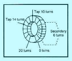
The Z match circuit and coil arrangement is shown in Figures 1 and 2. In winding the coil, the primary of 18 SWG enamel wire is evenly spaced around the core. This leaves a gap between turns in which the secondary of similar wire can be fitted in a second winding operation. To make a tap, one method is to clean off about a centimetre of the enamel on the wire at the appropriate point and fold half the cleaned part back on itself to form a terminal which is soldered. Winding is then continued.
Another method of forming the tap is to cut the wire at the tap point with a short end which is cleaned of enamel. The end of a new piece of wire is also cleaned of enamel and twisted with the other. Winding is then continued with the new piece of wire. The twisted wires are soldered to form the tap terminal.

Test Results
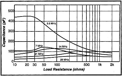
In testing the open coil AR Single Coil Z Match, load range tests were carried out over the resistance range of 10 to 2000 ohms at frequencies of 3.5, 7, 14, 21 and 28 MHz. The same tests were repeated using our toroidal core coil unit and this matched over the whole range, as did the open coil unit. Tuning curves, Figures 3 and 4 plot the capacitance needed in Cl and C2 over the load range. The curves show that the maximum capacitance for input capacitor Cl is 450 pF and for shunt capacitor C2 is 260 pF.

So far so good, but the bigh question concerns efficiency and possible loss in the core. In a previous article (Amateur Radio, September 1995) I described how I measured efficiency of a number of Z match units at 1,8, 3.5, 7 and 14 MHz. I have repeated the tests for the toroidal coil unit, refining the technique a little to extend the tests up to 28 MHz. For detail of' the measurement technique, you are referred to the previous article. The results of' the tests on the toroidal coil unit are given by Figure 5. This shows that efficiency is quite good over most of the load range at 3.5 and 7 MHz. At higher frequencies the efficiency falls and is particularly poor at 28 MHz.

In my opinion, loss of efficiency in the toroidal core coil is of more concern than in the open coil, Suppose we operate at a point on the efficiency curves which shows an efficiency of 60%. This represents about 2 dB loss which would be barely noticeable on the air. However. the 40% of power lost is probably dissipated in the iron powder core and, at high power. this might be sufficient to shatter the core. For this reason I would not be too enthusiastic to operate with high power when efficiency is low.
Another factor, which could set power limits on the toroidal core is the insulation resistance of the winding wire. For certain load conditions, quite high voltages can he developed in the Z Match. For example, with a 2000 ohm load at 3.5 MHz and a power of 100 watts, around 1000 volts is developed at the top end of the coil primary with potential to break down to the core. For the same load condition, around 600 volts is developed across the secondary with potential to break down to primary or to the core.
Of course, lower resistance loads produce lower voltages. For example, at 100 ohms load, voltage at the primary is around 300 and across the secondary around 140. However, one has to allow for all possible load conditions and perhaps an open circuit output condition. An arc-over condition in a tuning capacitor doesn't do much damage, but burnt insulation in the coil winding means a rewind.
There are various grades of enamel and other synthetic insulation on winding wire and I have not been able to obtain much information on the voltage ratings. General opinion seems to be that we are really testing our luck if we apply much more than a few hundred volts across the usual winding wire insulation. In my test unit 1 have used ordinary winding wire and this type of wire is probably quite OK for low power use. However, one might be well advised to use a better insulated wire for powers around 100 watts or more. Using the 18 SWG enamel wire, there is spacing between the turns of the windings and plenty of room for an increase of insulation thickness around the same diameter wire.
A recommendation for high voltage in one of the Amidon catalogues is to use Thermoleze insulated wire. They state that this has a very tough vinyl-like insulation having a voltage break-down potential of more than 2000 volts at a temperature of 180 degrees Celsius. They say that certain sizes of the wire are a stock line at Amidon.
Considering the factors I have discussed, there are clearly reservations about the use of this type of coil design in the Z match on the higher HF bands and at high powers. However, it takes up a lot less space than the open coil and could be attractive to some of the QRP operators who use only low power on 3.5 and 7 MHz where high efficiency is achieved. It is interesting to observe that if only these two bands are to be used, only the top section of C2 is required and there is no need for the split stator tuning capacitor unit. In this case, the circuit can be simplified to the diagram of Figure 6. This makes a slight difference to the load range curves for 3.5 and 7 MHz, but the whole load range is still covered. The arrangement also just tunes to the edge of the 10 MHz band but, if this band is used, it might be desirable to drop off one turn from the top of the primary. With the coil turns reduced, a little more than the maximum specified capacitance of 260 pF for C2 might also be needed to still tune 3.5 MHz.

For the QRP operator, there is also the possibility of using an iron powder core with the same two mix (red) material, but a little smaller than the 5 cm T200 I have used. Some smaller Amidon types are T157 (4 cm) and T130 (3.3 cm). I have not tried these but winding calculations to the nearest full turn are as follows:
For the T157, use 19 turns on the primary, tapped at 13 and 9 turns with a 5 turn secondary.
For the T130, use 21 turns tapped at 15 and 11 turns with a 6 turn secondary.
It is advisable to use the largest wire gauge possible. but in using a smaller core. there could be a problem in fitting in the 18 SWG wire specified in my, diagram. I anticipate that it would be necessary, to use a Iighter gauge wire on the smaller core.
Conclusions
A Single Coil Z Match Tuner design using an iron powder toroidal coil has been described. The design achieves a wide load resistance matching range as did the open coil AR Single Coil Z Match. The efficiency is good at 3.5 and 7 MHz but deteriorates at higher frequencies.
Some concerns have been expressed concerning power dissipation in the core when efficiency is low. This could lead to damage of the core when the unit is used at high power. The possibility, of breakdown of winding wire insulation when power is raised has also been considered.
For QRP users who mainly operate on the 3.5 and 7 MHz bands the toroidal core coil is an attractive proposition. Combined with miniature tuning gangs, which we have proved will work without arcing up to 25 watts, a very compact and efficient low power Z match unit can be constructed for 3.5 and 7 MHz. Although less efficient on higher frequency bands, the unit can also provide a useful service on these bands when required.
References
1. Lloyd Butler VK5BR -AR Single Coil Z Match - Amateur Radio, April and May, 1993.
2. Lloyd Butler VK5BR - Efficiency of the Z Match - Amateur Radio, September 1995
3. Lloyd Butler VK5BR - Analysis of' the Z Match Antenna Tuner - Amateur Radio, May 1989.