 |
A standard power supply for many transceivers is 13.8 volts at a maximum load of 20 amps. Radio Amateurs often build their own 20 amp regulated power supplies and various designs for these have been described in past issues of Amateur Radio (References 1 and 2). My own version of such a supply based on these designs was recently assembled but a problem seemed to emerge. How does one test such a unit to ensure that it can safely deliver 20 amps and how does one check its regulation? What is required is a 0.7 ohm resistor which can dissipate 276 watts. Just where does one get one of these ?
The solution was found in a coil of 16 SWG galvanized iron wire which was purchased from the local hardware shop for some other project around the home. The resistivity of iron is around eight times that of copper and 17.5 metres of this wire was measured to have a resistance of one ohm. I decided to start with one ohm so that the load current would initially be 13.8 amps. I was a little dubious about putting the full load on the supply until I had first had a look at temperature rise in the heat sinks at the lower power.
|
|
To check the value of wire resistance, a digital multimeter was used. This gives a more precise reading than an analogue meter, although the latter could be used if read with care. In any case, it is advisable to check the calibration of the instrument against several one ohm resistors which can normally be obtained from most electronic stores. Modern resistors can be relied upon to be very accurate (if operated well below their rated power). In measuring resistance the test leads were clamped tightly to the galvanized wire so that the joint did not add appreciable resistance error. Earth jointing connectors, used in power wiring, were put to good use for this purpose.
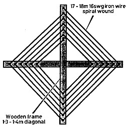
The galvanized iron wire was wound on a frame made from two 133 cm lengths of wood crossed at right angles (See Fig 1). Holes were drilled in each leg of the frame at various intervals and the wire was wound in a spiral through these holes until the wire ran out.
Mounting the wire test load on a frame made it more convenient to use adjacent to the test bench. I had considered running the wire down the back yard and back again or fitted to the back fence. There is nothing wrong with doing something like that, but I decided that it might be a nuisance if I needed to use the load for extended periods.
To connect the test load to the power supply, heavy copper wire leads were used so that negligible resistance was added by the connection. Of course the power connectors were again needed. For full load, the wire was ultimately tapped down to 0.7 ohm as measured at the end of the leads connecting to the power supply terminals. By measuring there, any connection resistance is included anyway.
At full load current of 20 amps, the dissipation in the wire is about 20 watts per metre (or .22 watts per cm) and the wire is just mildly warm. Of course a low temperature rise on load is important. Based on the temperature coefficient for soft iron, a rise in temperature of as much as 20 degrees centigrade would increase the resistance by 12% The power supply worked out fine once I had corrected an instability fault which initially showed up at full load. Without the test load, the fault would not have been detected. Regulation was measured as 0.35% which I considered acceptable. The galvanized wire had done its job. Perhaps someone else needs to test a supply and can make use of this cheap and simple idea.
References:
1 - Denzil Roden VK2BXF - "The Even Simpler Regulator" Amateur Radio, January 1980.
2. Des Greenharn VK3C0 - "13.8 V Regulated Power Supply" Amateur Radio, May 1983.