(Correction made in Sept. 2007 - see note)
Introduction
In the November 1995 issue of Amateur Radio, I discussed negative resistance and oscillator circuitswhich made use of the negative resistance characteristic. One type of circuit discussed used the tunnel diode and, as a further application of this diode, many radio amateurs will remember the tunnel diode dip meter kit available in past years from the Heath Company.
These days the tunnel diode is a scarce item, probably unobtainable from the normal electronic suppliers. An alternative solid state negative resistance circuit can be achieved by interconnecting an N channel junction field effect transistor (JFET) with a P channel JFET. This has been called the Lambda circuit because its characteristic curve looks something like the Greek upper case lambda (an upside down V) .
There have been various dip meter circuits published in radio amateur handbooks and in past issues of Amateur Radio. However, we haven't had one in Amateur Radio for some time and I thought I would introduce one around the concept of the lambda circuit. An advantage in using the negative resistance type of circuit, compared to one such as the Hartley, is that two terminal plug-in coils can he used.
I will first discuss the operation of the lambda circuit, then lead up to how an arrangement for the dip meter was devised.
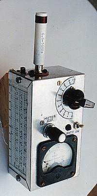
As assembled, and using a range of six plug-in coils, the dip meter operates over a frequency range of 1.6 to 150 MHz. It can also be switched to operate as an absorption meter.
Lambda Negative Resistance Circuit
Field Effect transistors can be classified between those which operate in the enhancement mode and those which operate in the depletion mode.
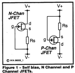
Enhancement mode means that the FET must be biased on to set the operating point for use as an amplifier (much like biasing a bipolar transistor). Depletion mode means that it must be reverse biased, or biased off, to set the operating point (as in a valve amplifier). The Junction FET or JFET operates in the depletion mode and to reverse bias a JFET stage, it is only necessary to insert an appropriate value of resistance in series with the source electrode (much like cathode bias in a valve stage).
Fig 1 shows a P channel JFET and an N channel JFET, each with a source bias resistor Rs. The only difference between the two circuits is the polarity in connecting to the supply rail. Voltage is developed across Rs and applied across the gate-to-source junction in reverse or depletion polarity. Due to the reverse feedback, the drain current is stabilised at a value determined by the value of Rs.
The curve of Fig 3 shows the drain current versus drain-to-source voltage, which I plotted for an N channel MPFI02 transistor and a P channel 2N4342 transistor connected in the lambda circuit. Up to point A, the drain current increases as the voltage is increased. Beyond point A, the current then decreases, with further voltage increase creating a negative slope and the negative resistance region A-C . The amount of resistance can be scaled off by taking the ratio of voltage change to current change along curve A-C and this is a value of around minus 1700 ohms.
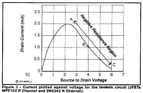
To make a negative resistance oscillator, we simply connect a tuned circuit in series with the lambda circuit, and the drain-to-source supply and set the supply voltage at, say, point B, around four volts. Provided the parallel resistance of the tuned circuit at resonance is somewhat greater than 1700 ohms, the circuit will oscillate and the oscillator circuit formed becomes the basis for our dip meter.
In principle, it is similar to the tunnel diode dip meter, but different because it requires around four volts as compared to the tunnel diode voltage of somewhat less than one. For more detail on the theory of negative resistance oscillators, I refer you to my article in November 1995 Amateur Radio.
Dip Meter Circuit
The circuit of the dip meter is shown in Fig 4. In my circuit I have used an N channel MPF102 (V1) and a P channel 2N4342 (V2). I was hoping to make my unit work well up into the VHF region, and there were a number of readily available and suitable N channel JFET transistors which could have been used. I selected the MPFI02 because I happened to have these. P channel JFETs seem to be more scarce and the only one I could find in the catalogues of the usual retail outlets was the 2N4342.

I was a bit dubious about using the 2N4342 as it was shown in my data sheets as a general purpose transistor and there was nothing to indicate how it might perform at high frequencies. With little else to choose, I bought some of these and gave them a try in the lambda oscillator circuit. As it turned out, I was able to make the circuit work at frequencies as high as 200 MHz.
To cover the tuning range in conjunction with plug in coils, a 100 pF variable capacitor (C2) is used. The only limitation is that on the top VHF band, the maximum setting of this capacitance must be limited to about 45 pF. At these frequencies, the circuit will stop oscillation if too much capacitance is used.
The Dip meter operates from a 9 V battery and the supply to the lambda circuit is stabilised by 5.1 V zener diode ZD1. To set the correct operating point, the lambda circuit supply is adjusted to 4 V with trimpot RVI. A switch, SW1, can be used to disconnect V1 -V2 so that the unit can operate in an absorption mode. Components C1, SW1, V 1, V2, and C2 are all part of the oscillator circuit and as it operates up to VHF, the lead lengths to these components must be short and earthing carefully commoned. Interconnecting the MPFI02 and 2N4342 works out quite well. Turn one 180 degrees to the other and the three leads on one connect directly across to the three on the other.
The idea of the dip meter is as follows: When the Dip Meter oscillator coil is placed near another tuned circuit, that circuit absorbs some of the energy from the oscillator. This causes a dip in oscillation level when resonance of the other circuit is found. Monitoring of the DC load current to detect this dip is often used with class C oscillators. However, the lambda oscillator works essentially in a class A mode and its load current does not vary greatly with change in level of oscillation.
To detect a dip in the oscillation level, the output voltage across the tuned circuit is monitored using a detector circuit which converts the RF voltage to a direct current to actuate a micro-amp meter or milli-amp meter. To prevent the detector loading the tuned circuit, it is coupled via a source follower stage V3, another MPF102 FET.
Two detector circuits are shown. If a 50 or 100 micro-amp meter is available, circuit A does the job. For a 1 or 2 milliamp meter, an additional current amplifier, V4, is needed and circuit B is used. In each case, the signal is rectified and filtered by voltage doubler C5, DI, D2, C6 and the following load resistance. For V4, almost any small signal silicon bipolar NPN transistor is suitable.
In explanation of one part of circuit B, the voltage developed across diode D3 forward biases the base of V4 to compensate for the residual voltage step set by its base-emitter junction. RV2 adjusts the sensitivity of the meter circuit so that it can he set at a suitable reading level.
Load current from the 9 V battery is approximately 14 mA.
Dip
As pointed out earlier, the oscillator will work provided the shunt resistance of the resonant tuned circuit is somewhat greater than the negative resistance value of 1700 ohms. Tuned circuits of even quite low Q factor have a shunt resistance of much higher than this and, hence, almost any practical inductor can produce oscillation. In effect, the feedback is greater than need be but the AC voltage developed is controlled because the voltage swing is limited by the extremities A and C on the curve in Fig 3.
As an oscillator source this is good, but it is not so good if looking for a dip in output level when energy is absorbed by a circuit being measured. With so much feedback, the circuit is still able to deliver the full signal swing when energy is absorbed and, hence there is little dip to be seen.
To produce a good dip, the shunt resistance of the tuned circuit is lowered to a point where the circuit just oscillates nicely and a little above the value which would stop oscillation. To achieve this condition, a resistor is shunted across the tuned circuit. As the optimum value of the resistor was found to be different for each band, the appropriate resistor for each coil is fitted at its base as part of its plug-in module. The selected value varies from 1.6 k.ohm to 4.7 k.ohm and no resistance at all for the top VHF band.
Coils
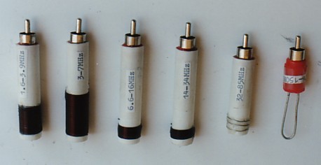
Finding a source of supply of small diameter insulating tube seemed to be a problem. Eventually I found a source of 0.5 inch (12.7 mm) diameter polystyrene tube at a local hobby train shop and this was ideal for the job. For the four coils which covered 1.6 to 34 MHz, I cut the tubing to a 57 mm length. For the 32 to 85 MHz coil, where the length of the wire from coil to plug was an accountable part of the total inductance, I reduced the tube length to 46 mm. For the highest VHF band, there is no former and the inductor is just a wire loop.
Coils are wound on the tube with the active end 3 mm from the tube end. The winding detail is shown in Chart 1. The ends of the coils are passed to the inside of the tube through holes drilled in the tube. A small amount of fast Araldite (trade name of Ciba-Geigy Corp) fixes the end turns in place.
I stress the small amount as I tried smothering one in Araldite and found that the stray capacitance increased sufficiently to reduce the tunable range.
| 1. 1 .6 to 3.6 MHz | 110 turns 40 B&S close wound | Shunt resistor 1700 ohms |
| 2. 3 to 7 MHz | 68 turns 28 B&S close wound | Shunt resistor 1600 ohms |
| 3. 6.6 to 15.5 MHz | 21 turns 28 B&S close wound | Shunt resistor 2000 ohms |
| 4. 14.3 to 35 MHz | 8.5 turns 28 B&S close wound | Shunt resistor 2000 ohms |
| 5. 32.3 to 86 MHz | 3 turns 22 B&S spaced to 8 mm long | Shunt resistor 4700 ohms |
| 6. 70 to 155 MHz | Wire loop 20 SWG TCC Length from plug terminals - 45 mm Loop width - 6 mm (av) |
No shunt resistor |
The RCA plastic plug cover is discarded and the resistor is soldered across the plug terminals. The leads from the coil, cut a little long, are also soldered across the terminals with the far end of the coil connected to the centre pin and the near end to the outer sleeve.
The remaining part of the plug assembly, with resistor and wires attached, is pushed into the tube as far as it can go without covering the plug connecting section. If necessary, the insulating material around the plug can be filed down to fit the tube. One version of the RCA plug I had on hand fitted nicely, but a new more recently purchased version had to be filed. The plug is cemented in the tube with Araldite.
Absorption Mode
With no shunt resistors across the coils, the instrument is very sensitive and has sharp tuning when operating in the absorption mode. Unfortunately, the need to add the resistors for the dip mode reduces the sensitivity and broadens the tuning in the absorption mode.The effect is most noticeable on the lowest two frequency bands. This is an unfortunate disadvantage, but one could easily make some extra coils without the resistor for absorption use on the low frequency bands.
In an effort to improve sensitivity in the absorption mode, I experimented with another scheme. The idea was to leave the lambda circuit in place for absorption mode and switch in a further shunt resistance sufficient just to stop the circuit from oscillating. The circuit then operated as a regenerative amplifier, increasing the sensitivity and raising the effective Q to make it sharper. A shunt resistance value of 2700 ohms was found to be suitable at HF but this had to be decreased to 1800 ohms at VHF to stop oscillation.
The idea worked quite well for HF, but it introduced a problem for the dip meter mode at VHF. The problem was introduced by the switch which switched out the extra resistor during dip operation. The few picofarads stray capacitance of the switch represented quite a low reactance at VHF. Hence, at these frequencies, the extra resistor wasn't really switched out and it upset VHF oscillation. Perhaps a low capacitance plug-in link in place of the switch might have been the answer, but haven't I persisted further with any tests along those lines. Anyway, I thought, it was worth mentioning as a workable idea for an instrument limited to at least the HF range.
Components and Assembly

The transistor circuit components were mounted on a small piece of matrix board of the type that has printed pads at each hole. Interconnection was then hard wired between pads. I stressed earlier the need for short leads around the oscillator circuit. Tag pins connected with short straps to the lambda FET stage, and at the edge of the board, were soldered directly to the RCA socket mounted on the dip meter box housing.
At VHF a common earth can be tricky. I had the oscillator circuit earthy end connected to the dip meter case at the RCA socket. It was also connected to case via the frame of the tuning capacitor. I initially experienced some form of anti-resonance with a drop out of oscillation near the middle of the 32-85 MHz band. I added a further common from the negative battery connection on the card to the case and the problem disappeared. At HF, wiring is not critical but, as frequency is increased into the VHF region, every wire strap is an inductance which might have to be taken into account.
Most of the main components used in the dip meter I had on hand. The small aluminium box, measuring 134 mm x 75 mm x 55 mm, was recycled from a past project and had originally been purchased from Dick Smith Electronics.
The miniature variable capacitor (measured capacitance range of 4 to 100 pF) and the meter were other recycled components. The meter was an old one, 56 mm square with a FSD of around 2 mA and an RF amp scale. I had a nice 50 micro-amp meter but it was too large to fit into the box, so 1 used the smaller 2 mA one with the extra circuitry B shown in Fig 4. The meter is only an indicator and what is shown on the calibrated scale is unimportant.
Whilst I have personally used a few recycled components, those specified can be found in the catalogues of the retail electronics shops. The only questionable item is the 100 pF variable capacitor, which is a component often more easily obtained from a disposals source.
A value for the resistor across each coil has been nominated. However, in repeating the circuit construction, it is possible that the optimum value might vary with the spread of characteristics of the two JFETs in the lambda circuit. The value might also he different if the design of the coil is changed resulting in a different coil Q. Low level of oscillation, or no oscillation at all, could indicate that the value is too low. Little indication of a dip when coupled into a resonant circuit could indicate that it is too high.
Calibration
To make the instrument useful, it must be calibrated on each tuning range against a calibrated frequency source or a calibrated frequency measuring device. The frequency source might be a signal generator or even another calibrated dip meter. The frequency measuring device might be a frequency counter or the radio shack tunable receiver.
Using a frequency counter, 1 found the easiest way was to place a one turn loop, connected to the counter, near the dip meter coil and then read off the frequency. Using the receiver, it is simply tuned in to find the dip meter signal. If the calibration of the receiver is not too reliable and a calibrated signal generator is available, just use the receiver as a monitor and reference the dip meter signal against that of the signal generator. There are various other alternative ways of doing the job.
The tuning dial must have some sort of scale and ideally the scale should show frequency calibration for each band. My box did not allow room for all this and I glued on a scale marked 0 to 10. The frequency scales were then plotted. against the decimal scale on graph paper and glued to the sides of the box cover, three frequency bands on each side.
Summary
The lambda negative resistance circuit and its application in a dip meter has been described. Using an MPFI02 and 2N4342 JFET combination, a frequency range of 1.6 to 150 MHz has been achieved. The circuit will oscillate using almost any practical inductive coil but, to get a good dip when power is absorbed from the coil, it must be carefully loaded with resistance to produce a tuned circuit of the right resonant shunt resistance.
The loading resistors reduce sensitivity and broaden the tuning when the meter is switched to the absorption mode. This mode is a secondary function but the loss of sensitivity is a disadvantage. The sensitivity can be improved by using separate unloaded coils or operating in the dip mode with the lambda circuit loaded down further below the point of oscillation.
Two metering detector circuits have been included, one for a 50 micro-amp movement and the other with additional DC amplification for a 1 or 2 mA movement.
The dip meter is a useful instrument to have in the radio shack, particularly for those radio amateurs who build or tune up their own transmitting and receiving equipment. A discussion on the uses of the dip meter has not been included as this is well written up in amateur radio manuals.
Footnote
The MPFI02 and 2N4342 FET transistor pair used to obtain the curve of' Fig 3, and used in the dip meter tested, were selected at random. Since writing the article, 1 have tested a number of other individual pairs of the transistors and have noted that, whilst each pair exhibited the negative resistance characteristic, there was a considerable spread of results relative to the curve shown in Fig 3. In fact, one particular combination had a maximum current at point A of less than 1 mA and did not want to oscillate too freely.
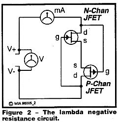
What I am saying is that, whilst my pair worked fine right from first go, it might be necessary to substitute one transistor, or the pair, if any oscillation difficulty is encountered. Also, if a voltmeter and milli-amp meter are available, it is not too difficult to set up the test circuit of Fig 2 to have a look in advance at the characteristic, and hence suitability, of any pair selected.
References
1. Lloyd Butler VK5BR - Negative Resistance Revived - Amateur Radio, November 1995.
2. Samuel Dick. - Exploring Negative Resistance: The Lambda Diode - Elektor Electronics, January, 1992.
Correction Sept 2007
Negative resistance derived from figure 3 was previously incorrectly given as -600 ohms. This has been changed in the text to -1700 ohms.