A "Sewer Pipe" Balun
Rob Gurr VK5RG
Over the many years association with Amateur Radio, I have used both coaxial cable and open wire line to feed the many antennas in use. Both have their advantages, however the open line is most suitable to multiband coverage. Feeding an open wire line into a radio room may be generally achieved without complication, and direct connection of the line to an Antenna Tuning Unit (ATU) can be made.
Some years ago I was faced with the need to bring such a feedline into a reinforced concrete building, where it was impossible to use open wire line, and the use of coaxial cable appeared more appropriate. An early method to overcome this was to use two short lengths of coaxial cable, with the open wire line terminating on the coaxial cable inner conductors, outside the building, and connected to two coaxial sockets mounted on the ATU inside the building. The ATU was tuned up in the normally accepted method for balanced line, and operated quite efficiently.
When moving to my present home recently, it appeared that I may have to again use the above method due to the house construction, however my attention was drawn by Phil Williams, VK5NN, to an article in "Radio Communications" for August 1992, where the use of one coaxial cable and a simple 4 to 1 Balun achieved the same purpose. The balun was wound on a piece of PVC Sewer Pipe, as may be obtained from a building site (with permission). This 4 : 1 balun was manufactured, tried on all bands from 3.5MHz to 28MHz, loaned to friends and members of the Adelaide Hills Amateur Radio Society, with remarkable success.
The balun was also tested at full Amateur power levels on these bands, without signs of overheating. The unit was mainly mounted on a facia board or other fixture, outside the building, with a short length of coaxial cable (RG213) connecting to an ATU inside. The ATU in most cases was a standard "Z" Match.
Whilst the balun has been used successfully on 1.8MHz, no definitive tests have been conducted. The author considers other methods of coupling may be more desirable on this band.
Theory of Operation
The impedance seen at the bottom of the feed-line, in a centrefed multiband antenna (centre fed Zepp) may vary from very low to perhaps a few thousand ohms. The generally accepted output impedance from an ATU is 50 ohms, and as few ATU’s are capable of performing over such a large range, it becomes convenient to reduce the upper impedance requirement to a lower value. This can be done with a 4 to 1 impedance transformer. The coaxial cable may be either 50W or 75W as its impedance is not important, but both windings must be the same.
The balun thus is performing a dual purpose...reducing the impedance range and also providing the required balance to unbalance function.
It is the purpose of this article to describe the use of the balun, and the theory may be found in Ref. 1 listed below.
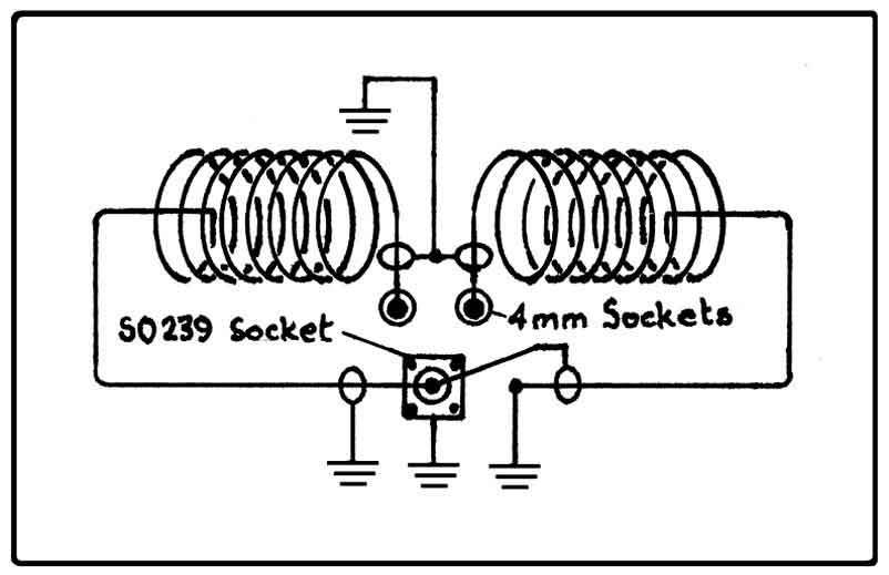
Circuit Diagram
Fig. 1. is a simple drawing of the balun. It consists of two 8 turn windings of coaxial cable laid up in opposite directions of lay. It will be necessary to study Fig.2 the complete balun, for fine detail.
Parts Required.
- 190mm long x 110mm OD (100mm ID) PVC Sewer Pipe former.
- 2 only 3.3m lengths of 50W or 75W small diameter coaxial cable, (typically RG58CU or UR67). Ensure the screen wire is copper, not aluminium.
- 1 only SO239 Socket
- 2 only Terminals for connection of the open wire feed-line.
- Qty of fixing screws, instant glue, solder and suitable iron.
- 1 only 150mm length of approximately 1.5mm diameter bare/tinned copper wire.
Construction
First determine the centre point on the former, drill holes and mount the coaxial socket, including washers and copper bonding wire as shown in Fig. 3. Drill and fit the two line terminals, 15mm apart near the coaxial socket but on the other side of the socket to the two cable holes. Refer to Fig 2.
Near the coaxial cable socket, and in line with the outer edges, drill 2 x 5mm diameter holes, approximately 30mm apart.
Drill another 2 holes, in line, a further 50mm away to allow for the 8 turns of cable.
Insert one end of each of the two coaxial cables through the centre 2 holes, and terminate the inners to the two open wire line terminals, and the outers (braid) to the copper wire bonding ring around the socket.
Wind tightly 8 turns of coaxial cables in each outwards direction, and pull the 2 loose ends tightly through the end holes. These winding are now in opposite lay on the former.
Next while the windings are held secure, fix them with instant glue, so they will not spring apart when the terminations on the socket are made.
The two outer ends of coaxial cable may now be terminated . Note from Fig.3, that the centre conductor of one cable end is terminated on the centre spigot of the coaxial connector, and the braid to the earthing ring. The centre conductor of the other cable end, is connected to the earthing ring, and the braid to the centre spigot
The balun is now complete.
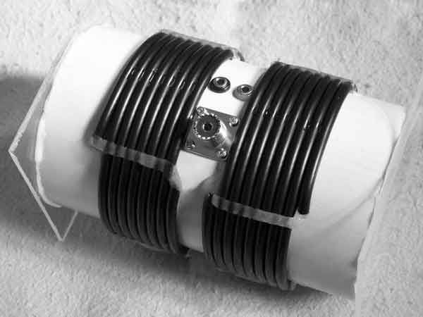
Note that Fig 2 shows the balun with the ends sealed to keep unwanted life from making it their home.

Fig. 3
Mounting
One method that may be used is to screw or bolt the balun under the eaves of a house, to give some water proofing, holding the former away from metal etc. with a couple of cotton reels. It is really your choice how to mount it, as long as the feed-line is clear from conducting material, and there is a drip loop to keep water away from the balun and coaxial cable and prevent entry of the water to the building.
There is no problem mounting additional terminals on the end surface of the former, in parallel with the original, to allow the use of much wider spaced lines. The balun described was used with 300 ohm open wire line when constructed.
References
1. "Radiocommunication August 1992 Page 51" RSGB
2. "ARRL
Antenna Handbook" any Edition 1942 to 2006
Acknowledgements
1. Photography by VK5ZNB Lyle Whyatt
2. Initial tests by VK5NN Phil Williams
3. Adelaide Hills Amateur Radio Society for extensive testing of demonstration models.
4. Editing suggestions by VK5ZNB Lyle Whyatt and VK5JST Jim Tregellas
|
Updated 03/01/2007 |