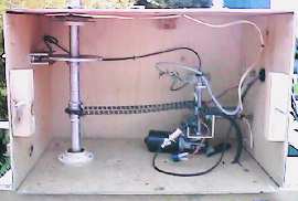
 For details about each component click on it in the diagram. |
 |
For details about each component click on it in the diagram. |
|

|
The infrared transceiver consists of two main parts.
|
|
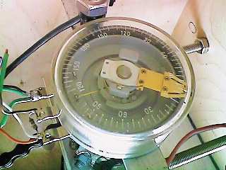
The purpose of the index disc is to assist in the detection of the rear of
the beam antennas. By detecting the same position in each rotation 'ROTOR HUNTER'
is able to provide results relative to the current vehicle direction. The rear of
the antenna (or index position) in detected when infrared light passes
through the hole in the index disc. This light is seen by the
infrared receiver and the index signal is
then passed on to the computer.
The index disc I use is made from aluminium, is about 150mm in diameter with a 9mm index hole. The center hole is 25mm in diameter to accommodate the antenna shaft. |
|
|
'ROTOR HUNTER' uses a variable resistor to indicate the position of
the motor drive shaft. The motor drive shaft is connected, by a
chain, to the
antenna shaft and both rotate together.
The variable resistor is a special type constructed to give a full 360°
rotation, not 270° as a normal potentiometer would. The unit I use was purchased at a garage sale for $3.00 and is the only one I have ever seen. It measures about 60mm in diameter and the shaft is about 6mm in diameter. It is mounted using two M6 screws which attach the body of the resistor to an aluminium plate which is then held in line with the sprockets and the motor shaft. It may be possible to build your own resistor using resistance wire and some type of round former. To view a close up image of the resistor click here. |
| A 100k resistor is connected between +5 volts and the center (or wiper)
contact to prevent an open circuit being seen by the parallel port interface
during the transition from full resistance to zero resitance.
The position indicating resistor is connected to the regulated 5 volt power supply from the parallel port interface with the center contact being connected to input Ø. |
|
|
The connection betwen the gear box shaft and the
drive sprocket is made with a
shaft adapter. This consists of a length of 12mm diameter mild steel
tube which slides over the
gear box
shaft and the sprocket shaft. The adapter
is held by two steel bolts which go through each shaft and the adapter.
Early on in the project I did it another way. To see how it was done before click here.
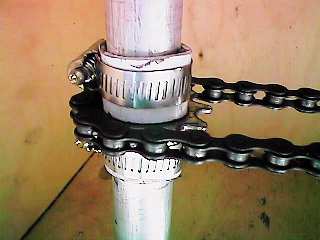
The position indicating resistor is connected to the drive sprocket by a length of PVC tubing. The tubing is held in place with two hose calmps and prevents any flex within the drive shaft from exerting force upon the position indicating resistor. |
|
|
The transmission of power from the motor to the
antenna shaft is done using
a chain drive. The drive sprockets I use were scavanged from a discarded toy tractor belonging
to my eldest son. He was quite pleased to see them get a 'second life'.
The sprockets are about 60mm in diameter. One sprocket has had a 25mm hole
drilled through it to allow attachment to the
antenna shaft. The sprocket
has a key hole filed in one side which aligns with a piece of 3mm rod.
This rod is held in place with two hose clamps and ensure the sprocket
remains attached to the antenna shaft.
The other sprocket is joined to the motor
shaft via a home brew shaft adapter. The sprockets are slightly different
sizes which initially caused the displayed signal to rotate 1 or 2°
each rotation. This problem was solved with the introduction of the
index disc
and a short routine within the 'ROTOR HUNTER' software.
To view a close up image of the drive sprocket click here. |
|
|
The DC motor and gear box used in the 'ROTOR HUNTER' are the type normally found driving windscreen wipers. The one I use has a parallel output shaft and is rated for 24 volt operation. Although I run it on 12 volts it performs very well. The output shaft rotates at about 25 RPM giving one sample every two and a half seconds. I tried a faster motor but the resulting pattern was not as sharp due the limitations of the receivers. |


Copyright 1999 - Peter Fraser - all rights reserved.