VK3ZPF TDOA PROJECT PAGE
|
In the search for the ultimate fox hunting weapon, late in 1998 I built a TDOA radio direction
finder.
The unit was designed by Joe, WB2HOL, and is described on his web site at
http://home.att.net/~jleggio/projects/rdf/rdf.htm.
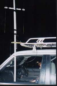
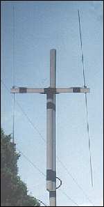
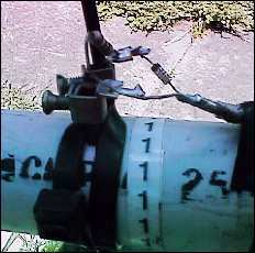
I constructed the antenna unit from a length of 25mm diameter eletrical conduit and the support
pole is 32 mm diameter conduit.
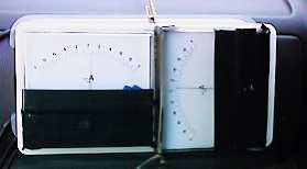
I made use of a center zero meter which was surplus to a local ham's needs. The TDOA unit works
very well with signals having vertical polarisation.
Horizontal signals can be DFed but the system is not as sensitive.
A further development of the TDOA principle is to use two fixed antenna arrays to provide a
quadrant indication. I have modified Joe's circuit a little and made such a system.
|
|
|
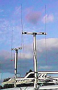
TWIN TDOA PROJECT
This system is similar to the one described above, except it uses two antenna arrays and
they do not turn.
The direction to the transmitter is shown on two centre zero meters.
|
Transmitter to the front
|
Transmitter to the rear
|
Transmitter to the right
|
Transmitter to the left
|
|
The circuit is shown below. The oscillator (IC3 F) runs at about 800 Hz and switches both
the antennas and the synchronous detector.
The divide by 32 counter (IC4) send pulses to either the for/aft or the left/right antennas and
their respective meter circuits.
A test switch is included to assist in orientation of each array and a phase shift circuit
has also been added to overcome any phase shift within the receiver.
At present one antenna unit is mounted on the car facing forward and the other is mounted on the
side facing to the right. This works well but the antennas have suffered a lot of damage from
low hanging trees.
The antenna refered to as the FOR/AFT is the antenna parallel to the side of the car.
That is, the transmitter will be directly to the right (or left) when the FOR/AFT meter
indicates zero.
|
My next improvement is an antenna array similar to those used for doppler systems. This would
allow for lower overall height and positioning in the centre of the roof. Two factors that will
help protect the array from abuse.
I am taking a good look at the new Roanoke doppler array by Joe Moell (KØOV).
You can find details of Joe's array at
http://members.aol.com/homingin/newdopant.html.
CIRCUIT DIAGRAM OF THE TTDOA
Junction of antenna, resistor and diode
|
Joe WB2HOL's antenna circuit
|


Copyright 1999 - Peter Fraser - all rights reserved.