 Figure
1 - Reflection of Signals from F2 Layer
Figure
1 - Reflection of Signals from F2 Layer
First back to basics! Figure 1 shows how 6M sig-nals from a transmitter TX are reflected back to the ground from the ionosphere, in this case the F2-layer. As signals enter the layer at lower and lower angles of incidence they reach the earth at greater and greater distances from the transmitter. This applies to reflections from both the F2-layer and the E-layer. The height of the E-layer is around 100 to 120 km at midday while the F2 layer is around 200 to 400 km. It is clear therefore that much greater single-hop distances can be achieved by reflections from the F2-layer than the E-layer. Multi-hopping from the F2 also allows propagation over much greater distances such as to Australia and Japan.
 Fig
2 - Angle of Incidence of Received Signals
Fig
2 - Angle of Incidence of Received Signals Fig
3 - H-plane Radiation Pattern for a Single 6-Element Yagi at 1.0 Wavelength
High
Fig
3 - H-plane Radiation Pattern for a Single 6-Element Yagi at 1.0 Wavelength
High
All of you, I am sure, are used to looking at an E-plane polar diagram of a horizontally polarised Yagi-Uda antenna showing such things as forward gain, front-to-back ratio and side-lobes on a decibel based scale. But with antenna stacking we are more inter-ested in the H-plane polar diagram. The H-plane lies at right-angles to the E-plane and shows the elevation or vertical radiation pattern of your antenna. Figure 3 shows the H-plane radiation plot of a typical 6-element Yagi beam at a height of one wavelength (about 20') above ground.
It can be seen that the main lobe peaks at an elevation of about 15° with the largest of many secondary lobes at 45°. This second lobe is only 6dB down on the main lobe so at least a quarter of your power is being wasted. If this and all of the other secondary lobes could be reduced then a lot more power could be sent to the DX rather than wasted. The reason as to why the main lobe lies on the -3dB line will become apparent later. As the antenna gets nearer to the ground the angle of radiation increases significantly to as much as 30° so this is why it is important to get the antenna as high as possi-ble above the ground and clear of all obstructions. The minimum height is probably about 1 and 1.5 wavelengths (20' to 30') before serious degradation of the radiation angle sets in. It can be estimated from the above plot that if a low-angle 8° F2 signal is received on an antenna such as this it could be down in signal strength by at least several dB compared to a better performing antenna and it could make all the difference between hearing a signal (or someone else hearing you) or not as the case maybe. For shorter skip Es propagation and meteor scatter work this antenna would be very effective with its large 45° lobe.
 Fig
4 - H-plane Radiation Pattern for Two Stacked 6-Element Yagis at 0.75 and
1.5 Wavelength High
Fig
4 - H-plane Radiation Pattern for Two Stacked 6-Element Yagis at 0.75 and
1.5 Wavelength High
On 6M it is very difficult to space Yagis 0.75 wave-lengths apart on a sensible sized tower. A much more practical spacing is between 12 to 16 feet (3.5 to 5 metres) with little degradation of performance. There is a price to be paid for the above advantages and this is reduced performance at middle-range angles of between 20° and 45°. Stacked antennas are not the best performers for short-skip Es and MS working. In reality though, the high signal strength of these propaga-tion modes on 6M means that you will never notice it. What are the important points to remember when stacking 6M antennas?
(1) Get your antennas as high and clear of obstructions as possible to keep the radiation angle low.
(3) Space antennas as far as part as possible, but if you can only manage 10' (3 metres) still do it!
(4) If you live in an electrically noisy environment lowering your angle of radiation might increase your noise level from local noise sources. It might also make TVI more prevalent, so beware!
(5) In my view it is better to spend your money on two smaller antennas and stack them rather than going for a single long-Yagi. Two stacked 4-elements is a good performer on 6M. Re-member also, two small antennas stacked could be far less visible than one gigantic long Yagi!
 Fig
5 - H-plane Radiation Pattern for Two Stacked 6-Element Yagis Fed In and
Out of Phase
Fig
5 - H-plane Radiation Pattern for Two Stacked 6-Element Yagis Fed In and
Out of Phase
The one downside of stacked antennas is the loss of performance in mid- to high-angle radiation and reception. Although you will probably never notice it, if you are a perfectionist and an experimenter there is a simple way around the problem. It is possible to electrically switch the radiation pattern between a low- and high-angle pattern. It is normal to drive the antennas in a stack with in-phase signals using a phasing harness such as described in the last SIX NEWS. This provides you with the optimum radiation profile as shown in Figure 4. If however, the antennas are driven out-of-phase by introducing an extra half-wave length of cable into one arm of the harness the radiation pattern switches high - up to as much as 30°! This is shown in Figure 5. By switching the half-wave piece of coax in and out with remote relays it is possible to experiment to see whether summer Es signals increase in strength when the antennas are fed out-of-phase - I am assured they do! Whether it is worth the extra effort and hardware will be left to your discretion! Another very simple way of overcoming the disadvantage is to wind the tower down as low as it will go thus increasing high-angle radiation!
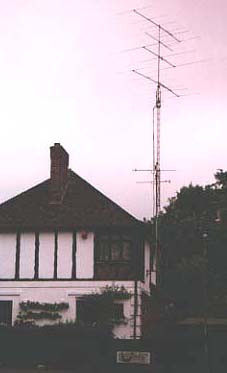 The
author's stacked 6 element beams.
The
author's stacked 6 element beams.It has been a general maxim in amateur radio for many years that if you have a spare pound to spend, spend it on your antennas first. This couldn't be more true than on 6M. So go and get stacked as I am confidant you will notice the difference on your first F2 opening with stacked antennas. To finish I can thoroughly recommend the following reading material if you want to know more about stacking antennas, the second reference is the bible on the subject. Both are available from the ARRL and RSGB.
(2,3,4) Taken from Yagi Antenna Design by Dr James L. Lawson, W2PV. Published by the ARRL (ISBN: 0-87259-041-0).
'Beam Antenna Handbook' by William Orr & Stewart Cohen. Published by the ARRL.
Article from U.K.S.M.G web site
Back Home