Phillip, VK3DCZ's Home Page
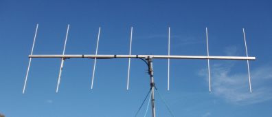
2 metre 7 element yagi beam homebrew project
Materials:
Boom made from 25mm square aluminium. A flat piece of aluminium to form
a shorting clamp between the DE & the Gamma Rod. A right angle piece of
aluminium to mount a SO-239 panel mount socket.A piece of wire. Nut,bolt and
washer. Elements are made from 12 x1mm wall round tubing & 10 x 1mm wall round
tubing. Gamma Match made from 12mm & 8mm or 6mm tube (could be ROD for inner
section) with insulating dialectric which can be heatshrink or outer coax cable
sleeve. Make sure they slide inside each other freely. Pop rivets. Zinc Plated
Outdoor type Steel screws. Perspex block. U bolt mounting clamp.
Spacing: REF to DE 16 inches, DE to DIR01 16 inches, DIR01 to DIR02 18
inches, DIR02 to DIR03 20 inches, DIR03 to DIR04 22 inches, DIR04 to DIR05 24
inches.
Boom Length 10 feet or 120 inches long so there will be 2 inches on each end
free. You could put 2 plastic end caps at the end of the boom.
Element lengths: SSB Reflector 104cm - Driven Element 98cm - All Directors
93cm
Element lengths: FM Reflector 102cm - Driven Element 98cm - Directors 93cm to
89cm ( Tapered for greater bandwidth )
Gamma Match: 12mm OD outer tube 7 inches long. 6 to 8mm ID inner tube 10 inches
long. Heatshrink and/or coax outer sleeve.
Spacing Between Gamma Rod and Driven Element centre to centre is 1.5 inches.
What I want to build is an adjustable antenna to change
frequency and get good bandwidth. Workout from the lengths above how much 12mm
OD tube length the main part of each element with 10mm OD tube at the ends to
adjust the length of each element. You can either screw to secure the two parts
together or if you desire cut a split in the bigger tube and use very small hose
clamps.
I'm using a gamma match as I find it easy to use, however
more bandwidth could be got by going to a folded dipole. The Spacing is designed
to give the best gain for the boom length. What you want to do is drill through
the boom to slide in the elements then you want to secure them with pop rivets
at the top so the elements are close to the top of the boom ( NOT mounted dead
centre ). Then it is time to setup the gamma match. Plexiglass, Perspex or other
UV resistant insulator block - drill four holes. One for the DE to pass through
and one for the gamma rod and two screw holes. Slide the block 3" long x 2" wide
onto the driven element with the top hole above which will be for the gamma
match outer tube. When the block meets the boom, secure it with two self-tapper
screws which will be under and to each side of the driven element. Make the
gamma match using the smaller 10" long rod/tube and fit the dielectric (
heatshrink etc )
Then slide it into the larger 7" long tube to make a
reasonably firm but easy to slide fit. Put it in the top hole facing out along
one side of the driven element. Now get a section of flat aluminium sheet cut it
to a strip about 1" wide and around 6 to 8" long. ( use your own judgement )
Bend the strip around the DE and Gamma tubes so that the ends meet in the
middle. Drill a hole in the middle to secure it with nut, bolt and washer. That
is your shorting strap. This strap will be about halfway along one side of the
DE roughly 10" from the booms' centre point. Make a right angle from the
aluminium flat sheet big enough 2" x 2" to fit the chassis mount SO-239 socket. Drill out and file/ream a
hole big enough to put in the SO-239. Secure it by whatever means. Drill two
holes on the other bottom part and screw mount it to the beam's boom near the
gamma match. Solder the inner of the SO-239 with a wire ( keep short ) and
solder on a spade lug on the other end which you attach to the outer tube - a
small bolt, nut and washer is what I used. A bit of Selley's Silastic clear is
used to waterproof it. Find the balance point of the antenna somewhere near the
middle and drill, file and install two holes for the " U bolt mounting clamp. "
The Yagi beam is now ready for testing. I temporarily mount it on a PVC non
metallic mast and attach a short RG58U jumper cable to my Antenna Analyser or
SWR meter and radio if you don't have an analyser. First thing to do is find the
centre resonant frequency of the beam which should be where the SWR is lowest.
Then slide in or out your gamma rod to lower the swr. Also try moving the
shorting clamp to get the lowest swr.
I'm getting 2Mhz bandwidth 2/1 SWR or 1Mhz bandwidth
1.5/1 SWR.
You now are ready to screw on the coax ( RG-213, 9913,
9914 ) PL259 to PL259 or N Plug depending on what you need. A run of 10m to 15m
would be OK.
Personal Interests: Amateur Radio & Internet/Building Antennas/Reading eBooks/Science
Fiction/TV & Films.
See Martins' WWARG on Talkforce, Zello and
Echolink.
- Internet VOIP program for Amateur Radio communication
-
- Echolink VOIP
***************** DISCLAIMER
*******************
Much of the content on this
site depends heavily on the information supplied to me
by others, and whilst EVERY effort has been made to ensure the accuracy of this
Website, I CANNOT guarantee the accuracy of the information you will find on
this site.
The content of the vk3dcz
web site is provided for information purposes only. No claim is made as to the
accuracy or authenticity of the content of the web site. vk3dcz does not
accept any liability to any person for the information or advice (or
the use of such information or advice) which is provided on this web site or
incorporated into it by reference.
The information on the vk3dcz web site is
provided on the basis that all persons accessing the site undertake
responsibility for assessing the relevance and accuracy of its content.
The information contained in
the vk3dcz web site is not to be displayed except in full screen
format. No liability is accepted for any information or services which may appear in
any other format. No responsibility is taken for any information or
services which may appear on any linked web sites.
Phillip vk3dcz...... vk3dcz
2015-2016 All Rights Reserved.
Email:
[email protected] or
mailto:[email protected]
[email protected]