
A.679-H FRONT VIEW
| VK2DYM'S MILITARY RADIO AND RADAR INFORMATION SITE. |
HIGH FREQUENCY RECEIVER MODEL AMR.300
and the A.679-H, A.679-J and A.679-K versions.
A.679-H FRONT VIEW
The A.679-H communications receiver was manufactured by Standard Telephones and Cables Pty. Ltd. (STC) in Sydney during the period 1943-1944. To meet a requirement for Direction Finding systems it was modified to become the A.679-J. It underwent further modification to be the A.679-K. When purchased by the Australian Army it became the AMR.300, in late 1944-1945. The AMR.300 was used by all Australian armed forces and was supplied to the US Army Signal Corps as the SC-CD-312-44.
GENERAL DATA FOR ALL MODELS.
The intended function was as a high grade receiver for
telephony, and CW and MCW telegraphy signals. The design parameters included
withstanding temperatures up to 70°
C (158°
F) and damp tropical climates with temperatures up to 50°
C (122°
F) and relative humidity up to 100%.
The receiver covered 1.5 M/cs to 24 M/cs in 4 band switched bands as follows:
| MAXIMUM | MINIMUM |
| 24 M/cs | 12 M/cs |
| 12 M/cs | 6 M/cs |
| 6 M/cs | 3 M/cs |
| 3 M/cs | 1.5 M/cs |
The overall sensitivity of the set was such that it produced 50 milliwatts output across the full frequency range with a 2 microvolts input. The signal to noise ratio was better than 2 to 1 for a 2 microvolt input.
The selectivity with the crystal filter out of circuit
At ±
6 Kc/s off resonance
--
20 db down
At ±
12 Kc/s off resonance
--
40 db down
At ±
18 Kc/s off resonance
--
60 db down
With the crystal filter switched in and correctly adjusted the maximum bandwidth was 200 cycles.
Attention was given to frequency stability such that after 10 minutes warm up the frequency drift on any range was less than 0.05% of the operating frequency.
The receiver was designed to operate from 110v ac or 240v ac, at 40 to 50 cycles. Two power leads were supplied, a 2 pin version for 110v which plugged into a 2 pin socket and a standard 3 pin lead for the 240v input socket. The power consumption was approximately 65 watts.
In addition the set could be operated from a 12 volt battery using the optional vibrator power unit. The consumption was approximately 60 watts on battery power. The vibrator Power Unit was 6 1/4"wide x 13" deep x 6" high (159mm W x 330mm D x 152mm H).
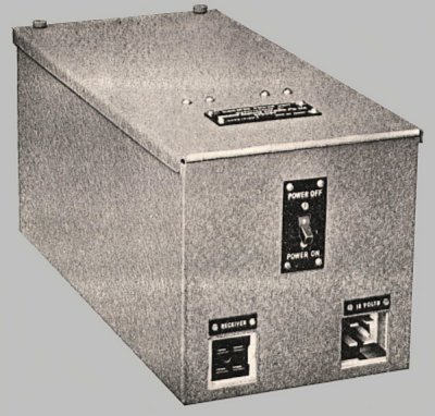
VIBRATOR POWER UNIT
The vibrator power supply unit used a non-synchronous vibrator and two 6X5GT rectifier valves. It was housed in a steel case with a hinged lid. A spare valve and vibrator were mounted inside, in dummy sockets. All valves and vibrator were securely fastened via base clamps. There was also space inside the case for the two battery power leads.
The receiver weighed approximately 74 pounds (33.5 Kg). Dimensions were 21” wide x 12” depth x 11 ½” high (534mm W x 305mm D x 292mm H).
The circuit used 9 valves as follows:
V1 6U7G 1st RF Amplifier
V2 6U7G 2nd RF Amplifier
V3 6K8G Frequency Converter
V4 6U7G 1st IF Amplifier
V5 6G8G 2nd IF Amplifier and 2nd Detector
V6 6B8G Audio Amplifier
V7 6V6G Output Stage
V8 6J7G Beat Frequency Oscillator
V9 5V4G High Tension Rectifier
The valve sockets had base clamps to keep the valves locked in place.
The aerial circuit of the A.679-H was designed for a 80 ohm doublet
The aerial stage, the 1st and 2nd RF and the oscillator were tuned by a four gang variable capacitor driven by an 80:1 vernier reduction drive with a 180° dial and pointer. The aerial had a small vernier capacitor for fine adjustment.
The IF frequency and of course the crystal were on 455 Kc/s.
A.679-H
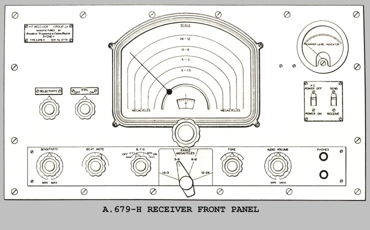
The nameplate on the above drawing states "HF Receiver Group
2A" and at the bottom it has "A.679-H and the serial no."
FRONT PANEL CONTROLS - A.679-H - from centre left:
SELECTIVITY. A small variable capacitor varied the neutralising of the crystal and hence the bandwidth, with the crystal in circuit.
XTAL OFF – ON. Self explanatory.
MAIN TUNING DIAL with an 80:1 reduction with 4 scales and a pointer plus a small logging scale with 100 divisions at the bottom. The tuning mechanism was fitted with a flywheel for rapid band traversing and a brake to prevent damage at the limits of the travel. The markings of each band were colour coded, eg. red, blue, orange and green and these colours are repeated on the band change switch.

Main dial showing colour coding to match the Band Change Switch.
CARRIER LEVEL INDICATOR. A 0 – 1ma meter calibrated in both R units and db, the reference level being a 2 microvolts signal with 30% modulation.
AC POWER SWITCH. Self explanatory. When the set was powered from the vibrator supply the ON-OFF switch on that supply controlled the receiver power.
SEND – RECEIVE. A single pole switch to control the high tension to the RF amplifiers, the IF and the Frequency Changer so that an adjacent transmitter can be operated.
On the engraved lower panel the controls are:
SENSITIVITY. A 28 stud wire wound attenuator controlled the gain of the two RF and 1st IF stages.
BEAT NOTE. The beat note control potentiometer allowed a ± 3000 cycle variation in beat frequency.
B.F.O. OFF – MAN – AVC – ON – MAN – AVC. The four positions of the switch acted as follows:
OFF – MAN BFO off – AVC off
OFF – AVC BFO off – AVC on
ON – MAN BFO on – AVC off
ON – AVC BFO on – AVC on
RANGE MEGACYCLES. A four bank rotary switch to change bands. The engraving was colour coded to match the coloured tuning scales.
TONE. This is a 5 position switch adding resistances to attenuate the higher frequencies in the output stage.
AUDIO VOLUME. The audio volume control was another 28 step attenuator calibrated in 2db steps.
PHONES. Two standard post office style headphone jacks were provided to suit 5000 ohm headphones.
Other controls were:
DIAL LIGHTS. The two dial lights could be switched on or off via a switch inside the cabinet.
METER ZERO SET. The S-meter could be set to zero via a pot inside the cabinet. These last two controls could be accessed by lifting the hinged lid of the cabinet.
LINE OUPUT. On the rear of the chassis was a 600 ohm line output socket which could alternatively be used with a speaker.
AERIAL TERMINALS. There were A1 and A2 terminals to suit a doublet aerial and an E earth terminal.
==================================================================================
A.679-J
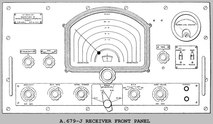
DIFFERENCES APPLICABLE TO THE A.679-J:
A Faraday shield was fitted between the primary and secondary of each aerial transformer thus making the receiver suitable for use in Direction Finding systems.
AERIAL VERNIER. An Aerial Tuning Vernier was added to the front panel, in place of the BFO which moved to the Tone control position, which was shuffled up to the right of the main dial. The aerial vernier was connected across the secondaries of the aerial transformers to allow fine tuning with various aerial systems. Because the aerial transformers could be direct tuned, the trimmers and padders across each coil (as used in the A.679-H) were deleted. The addition of the Aerial Tuning Vernier necessitated an alteration in the front panel layout.
As mentioned above, allowed fine tuning of the aerial circuit to suit different aerials.
The band change switch was changed to five gang, to switch both sides of the aerial coil primaries.
The RF section now had 5 shielded compartments with the aerial coils occupying two compartments instead of one.

A.679-J FRONT VIEW
The A.679-J was specifically designed to fit into a weatherproof, canvas covered wooden carry case that had 4 legs on it to double as an operating desk in the field. The carry case was self contained and included a vibrator power unit and a drawer to hold the speaker and two headphones with another drawer for spare valves etc. Aerials and power leads fitted in a compartment at the top left of the case. The receiver and power supply were mounted on anti-shock cradles with provision for quick removal. Small doors on the rear of the case gave access to the line and aerial terminals. Note: the A.679-H did not have the mechanical attachments and could not be substituted into the carry case.
===================================================================================
A.679-K

The nameplate on this model has "US ARMY SIGNAL CORPS" at the top, with "HF Receiver Model AMR-300" followed below with SC-CD-312-44. Others have just "HF Receiver AMR-300" and "Type A.679-K"
The AMR-300 (A.679-K) had the electrical changes of the A.679-J but used the cabinet of the A.679-H, ie. it could not be fitted into the carry case of the A.679-J.
In addition another switch was added to the front panel to provide a reading of the line output in addition to the signal strength on the meter. This switch was added to the left of the meter and was marked as follows:
METER READS DB - DB+20 - SIG. In the first position the meter reads the audio output signal direct in db with a scale of –6db to +14db. Position two adds a 20db pad so the output reading must have 20db added. In the third position the meter acts as an S-meter reading the incoming signal in units of 6db, from R1 to R9, where R1 corresponds to a signal input of 2 microvolt, modulated 30%. The AMR.300 manual says the meter was changed to a 0 – 0.86ma meter to suit.

AMR.300 (A.679-K) FRONT VIEW
Internally all three sets appeared similar so only the AMR.300 is shown:
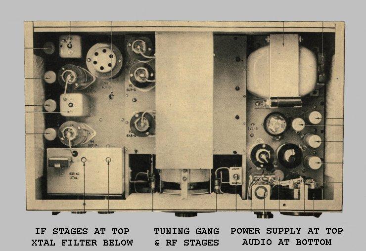
The mechanical construction of the set was most impressive and probably expensive. The chassis was of cadmium plated steel, with a louvred steel cabinet (with hinged lid) in stove grey crackle lacquer.

AMR300 (A.679-K). The colour is more grey than shown here.
The RF and Frequency Converter sections were mounted on a cadmium plated brass sub-chassis with 4 shielded compartments for the various stages. Each RF transformer and trimmer capacitor assembly was on a separate insulating plate for isolation and quick removal if needed.
The BFO was inside a separate cadmium plated copper box mounted under the chassis.
The tuning mechanism used a metal bellows to connect the gear drive to the tuning capacitor. The gear mechanism was enclosed in a cast metal box filled with grease. Backlash was minimized by spring loading of the gears which had been lapped for accuracy.
The set was treated for tropical conditions and was screened to prevent ingress of insects.
As can be seen from the above specifications this was a very high quality communications receiver, for the time, probably better than the more famous AR7.
References.
Instruction Book for HIGH FREQUENCY RECEIVERS TYPES A.679-H and A.679-J. Standard Telephones and Cables Pty. Ltd.
Sydney, Australia 1944
Instruction Book for HIGH FREQUENCY RECEIVER MODEL AMR.300. Standard Telephones and Cables Pty. Ltd. Sydney, Australia 1945
Please note, this article is copyrighted.