
| VK2DYM'S MILITARY RADIO AND RADAR INFORMATION SITE. |
RECEPTION SET No. 4 (Aust.)
The Reception Set No. 4 (Aust.) was designed for interception reception and general communications in both mobile or fixed locations, on radio telephony (RT), wireless telegraphy (CW) and modulated wireless telegraphy (MCW) in the range 1.2 Mc/s (250metres) to 20 Mc/s (15 metres). It was also the primary set for use with the Wireless Set (Aust.) No. 133 and the secondary set for the WS No. 22. It was made for the Australian Army by the Australian Philips organisation.
The frequency coverage was arranged in four switched bands as follows:
|
BAND A |
1.2 Mc/s |
3.3 Mc/s |
|
BAND B |
3.3 Mc/s |
8.2 Mc/s |
|
BAND C |
8.2 Mc/s |
13.8 Mc/s |
|
BAND D |
13.8 Mc/s |
20 Mc/s |
The sensitivity varied from 1-2 microvolts input on CW to 2-4 microvolts input on RT for a 50 milliwatt audio output, across the bands.
The selectivity was:
At ± 3 Kc/s off resonance
-
6 db down
At ± 7 Kc/s off resonance
-
20 db down
At ±
20 Kc/s off resonance
-
60 db down
The No. 4 could be operated from 110, 220, 240 or 260v ac, 40-60 cycles and also from a 6 volt battery. In addition to the ac power supply the set had an internal vibrator. The power consumption was approximately 35 watts on ac and 4.5 amps with the 6v dc supply. The power transformer had screw terminal taps for various input voltages, accessible after removing the set from its case. There was extensive filtering on both the dc and ac lines to minimize interference.
It weighed approximately 41 pounds alone (18.6 Kg) but with accessories and protecting cover the all up weight was 66 pounds (30 Kg). Dimensions of the set only were 19 ½” wide x 10 ½” deep x 9” high (483mm W x 267mm D x 229mm H).
The valve line up was:
V1A
6U7G
RF Amplifier
V2A
6J8G
Frequency Changer
V3A
6G8G
IF Amplifier, 2nd Detector, AVC
V2B
6J8G
1st AF Amplifier, BFO
V3B
6G8G
2nd AF Amplifier
V4A
6X5GT
Rectifier
V5124
6v vibrator
(The manual uses V2A and V2B just to indicate that the valves are the same type.)
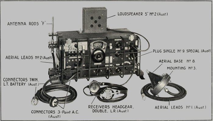
The aerial input was designed for versatility with a range of fixed or mobile aerials. The set was supplied with a selection of Type F antenna rods and an Aerial Base No. 8 for operation whilst on the move, plus a lead and counterpoise for a temporary field location as well as a horizontal aerial for a fixed setup. A doublet aerial could be made up and used for optimum fixed frequency performance.
Tuning was accomplished with a “Muirhead” style reduction knob with direct drive from the rear disc and a slow motion function from the front disc. The three gang tuning capacitor has a range of 12-420mmfd .The wavechange switch operates a rotatable mechanism with a disc with masking slots so that only the band in use shows up on the dial window.
The IF frequency was 455 Kc. There was no crystal filter.
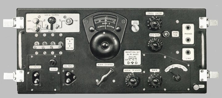
The front panel controls are – from top left:
AERIAL SWITCH HZTL – DOUBLET – VERT and Aerial terminals. Reflecting it’s purpose of mobile or fixed operation there are screw terminals for a horizontal wire and earth as well as a Pye coaxial coupling for a vertical antenna. The 3 position aerial switch allows selection of the various options and earthed the unused positions.
TUNING DIAL. As indicated above the Muirhead dial has an inbuilt direct/slow motion operation. The dial scale indicates direct in Mc/s and only the band in use shows in the dial window.
DIAL LOCK. To the right of the tuning dial is a screw type dial lock.
CRASH LIMITER. A potentiometer to control the shunt effect of two back to back metal rectifiers across the secondary of the audio output transformer. In operation the rectifiers offer a high resistance to normal audio voltages but that resistance decreases rapidly for higher voltages (such as static crashes), effectively shunting the voltage to earth. The crash limiter adjusts the operating point of the shunt effect.
POWER SWITCH AC ON – OFF – DC ON. A Heath Robinson affair of four center-off double throw toggle switches to control the power supply from the mains or the vibrator. If operating from a battery, one switch feeds 6 volts to the vibrator and a second one applies 6 volts to the filaments. On mains supply both input leads are switched by the other two toggle switches.
BFO NOTE. Over on the right of the panel is a conventional BFO with an approximately ± 2000 cycle range.
SPARE FUSE. At least it is readily at hand if needed.
PHONES. Two standard issue headsets can be plugged in, or alternatively the small 5” (127mm) speaker that was issued with the set.
LINE. A standard 600 ohm line output socket.
DC SUPPLY. A standard military 2 pin connector. The DC filtering components are also attached to the back of this sub-panel, as is the fuse.
FUSE. The fuse is in the 6v dc input line.
AC SUPPLY. A standard military type 3 pin connector.
WAVE CHANGE. A substantial lever which operates a Geneva type mechanism to change bands and rotate the dial window with a satisfying “kerchunk”.
AERIAL TRIMMER. The aerial trimmer capacitor allowed fine tuning of whatever aerial was in use.
GAIN. To control both RF and AF gain. Interestingly the RF and Audio gain pots are separate but ganged together via a gear drive behind the front panel.
OPERATIONS SWITCH - STD BY – RT – CW – MCW. Self explanatory. Note that the Gain and Operations Switch knobs and the sub-panel could be removed to gain access to the controls behind the front panel.
EARTH. A second earth terminal as an alternative to the one on the aerial switch location.

The best description of this set would be “utilitarian”. It was sturdily constructed to withstand rough handling and used basic readily available components so some compromises in construction are apparent. There is certainly nothing pretty about the appearance, with a black crackle paint finish, although the silver coloured background behind the engraved designations may have been to “pretty” it up. The front panel is spaced out from the main chassis to accommodate the dial mechanism and the power supply and the gain controls and operations switch.

FRONT PANEL REMOVED, SHOWING BAND CHANGE AND RF/AF VOLUME CONTROL
The chassis was plated and the components tropicalised.
References.
Signal Training Vol.III, Australian Pamphlet No. 13,
RECEPTION SET No. 4 (Aust.) 1943.
Please note, this article is copyrighted.