
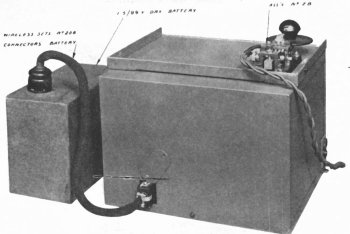
WIRELESS SET No. 208. Hinged lid open and battery block at right.
| VK2DYM'S MILITARY RADIO AND RADAR INFORMATION SITE. |
WIRELESS SET No. 208, 208* AND 208 MARK II
WIRELESS SET No. 208. Hinged lid open and battery block at right.
The Wireless Set No. 208 was developed for the Australian Armed Services in early 1941 as a low power portable transceiver capable of CW transmission only. It was intended for communications within an infantry battalion or similar.
The 208 shares the same chassis as the WS 108 and was also made by Radio Corporation Pty. Ltd. in Melbourne. See my web page for the WS No. 108 which was a very similar set - for voice only.
The WS 208 could be carried in a backpack or rucksack but could only be operated whilst on the ground. (The WS 108 could be operated on the move). The frequency range was 2.5 Mc/s to 3.5 Mc/s. The IF frequency was 455 Kc/s.
In late 1941 a modification kit was issued to introduce significant changes to the set and it became the WS 208*. The same changes were incorporated in factory production, along with further modifications, to produce the WS 208 Mk. II.
WS 208.

WS No. 208 Complete Station. Top right is the battery block.
The 208 was installed in a sheet metal case with a front lid hinged at the top so that it folded back on top of the case. The morse key could then be attached to the lid for sending.
Whereas the WS 108 had a case big enough to house the batteries, the 208 had a separate battery block of 99V HT and 1.5V LT with a 4 pin socket built in. A battery cable connected this block to a 6 pin plug on the rear of the set. In addition, an adaptor cable was provided, with terminal pins so that two separate 45V and one 1.5V batteries could be connected, as per the WS 108 Mk. I. The power output of the set was 0.5 to 0.5 watts depending on the frequency and length of aerial.
 |
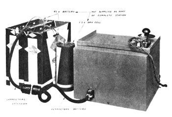 |
| Rear view with battery block on left with connecting cable. A small metal plate covered the battery cable opening in the case when not in use. | When using separate batteries an adaptor cable was added, with wires to fit the spring terminals on the batteries. |
The data on the WS 208 is as follows:
| SENDING (ma.) | RECEIVING (ma.) |
| LT | HT | LT | HT | |
| Current Consumption | 200 | 18 | 250 | 8.5 |
| WEIGHT (lbs) | LENGTH (in.) | WIDTH (in.) | HEIGHT (in.) | |
| Sender/Receiver | 8 3/4 | 9 1/2 | 8 | 7 |
| Bag, Accessories | 4 1/2 | 8 | 7 | 5 |
| Battery (1.5/99) | 5 | 6 3/4 | 3 1/2 | 5 1/4 |
| Complete Station | 18 1/4 |
The WS 208 was significantly smaller and lighter than the WS 108 (40 lbs complete) and reportedly was used and favoured by commandos and coast watchers.
The WS 208 was only used with a long wire and counterpoise (Marconi type) and was supplied with 60 feet of rubber insulated flex and a 12 feet star counterpoise as well as two cords with insulators for slinging the aerial over tree branches etc. The aerial wire and counterpoise lead each had a phone tip on the end to attach to the aerial and earth terminals on the set.
The
valve line up was as follows:
V1A 1P5GT Tuned RF amplifier
V1B
1P5GT
1st IF amplifier
V2A 1A7GT
Frequency changer
V3A
1D8GT
2nd Detector, BFO and AF amplifier
V4A 1Q5GT RF
Oscillator
V4B
1Q5GT Power amplifier
 |
 |
| LEFT-REAR VIEW OF WS 208. Note battery plug. | RIGHT-REAR VIEW OF SET. |
The
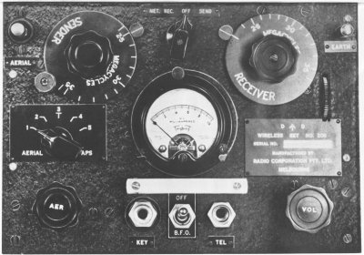
controls were, from top left:
AERIAL A spring loaded terminal to accept the Phone tip connector on the
aerial wire.
SENDER Tuning dial with a dial lock at bottom left corner and the frequency
indicator pointer at top right.
SEND-OFF-RECEIVE Switch.
RECEIVER Tuning dial with the frequency indicator pointer at top left and
a vernier control thumbwheel at the lower right.
EARTH terminal with spring loading.
AERIAL TAPS switch with 5 positions.
METER used for dipping the transmitter tuning.
NAME PLATE which had D^D (for Department of Defence), WIRELESS SET
No.208, SERIAL No., MANUFACTURED BY RADIO CORPORATION PTY. LTD., MELBOURNE
AER Aerial tuning knob which rotated two turns across the full range.
KEY socket for morse key
TEL socket for headphones
BFO pitch control knob combined with BFO On/Off switch. The BFO was tuned
via a trimmer capacitor through 180 degrees and the BFO OFF switch operated when
the control was fully clockwise.
The Aerial Taps and Aerial Tuning were only operational on the transmitter loading coil.
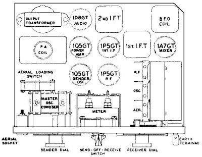
WS 208. The layout is similar to the WS 108.
Note the aerial socket on the above drawing. In production this was changed to a spring loaded terminal, the same as the earth terminal.
WS 208*
In late 1941 a major Modification Kit, ZAA 8840, consisting of 59 new items (161 separate components), was introduced and the WS 208 set was modified in the field workshops to include a Volume control, Netting facility and BFO On-Off switch. A new integral battery cable was fitted and a number of internal coils and components changed. The front panel had to have holes drilled and the rear of the case was modified so that the set would sit correctly in the case, with the new battery cable. The receiver tuning gang was removed and one of its support pillars shortened and an additional bracket added upon re-assembly. All valves were fitted with shields. Finally the set was tropic proofed. To accomplish this the kit included a bottle of Taubmans Bakelite Varnish No. 5730 and a paint brush. In addition the aerials and counterpoise from the WS 108 were supplied.
The end result was that now the set had a netting facility, a volume control and the BFO had a simple On-Off switch. The battery cable was permanently attached to the set and it was now tropic proofed.
WS 208*. Note new NET-REC-OFF-SEND switch and Indicator Plate, a new
perspex cover over the meter,
a new Withdrawal Bar, a new BFO switch and Indicator Plate and a new VOL
control. A star "*" was to be
stamped next to the 208 on the nameplate but that doesn't appear to have
been done on this example.
 |
 |
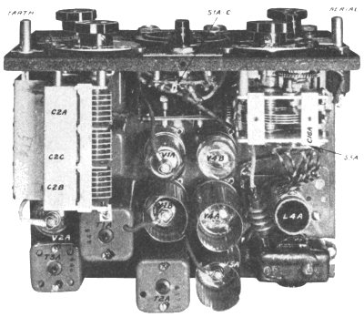
| WS 208. To make the modifications, T1A, T2A, T3A and L4A were changed, as well as L1A, L2A, L3A, L5A and L6A under the chassis. Shields were fitted to V1A, V4B and V2A. | WS208* after modification, with a new battery cable, new transformers T1A, T2A, T3A and coil L4A. All valves now have shields. The switch at top centre is now a 9 pole 4 position switch. |
WS 208 Mk. II.
The next model, introduced in early 1943, incorporated all the changes that were made to the WS 208* and in addition the aerial taps switch was changed to the WS 108 Mk. III type with 10 positions, to better suit the long wire aerials of the WS 108 Mk III which had been supplied starting with the WS 208*. The battery cable was repositioned to the front of the set to help in shower proofing the case. The volume control was moved a little to the left to make room.

WS 208 Mk. II. The obvious differences to the WS 208* are the10 position
Aerial Taps switch,
different nameplate data and the front mounted battery cable.
Incidentally, note how the nameplate of the WS 208 was the blank size from the WS108 and because the WS 208 is a smaller set it had to be notched to clear the receiver vernier knob. Also note that rather than having an engraved front panel as per the WS108, the WS 208's had engraved indicator panels attached with small drive pins.
see also my web page on the WIRELESS SET No. 108.
References.
Signal Training Volume III, Australian Pamphlet No. 8, Wireless Set No. 208,
1942
Instruction Manual for Wireless Set No. 208 Modification Kit.
Please note, this article is copyrighted.