WIRELESS SET No. 108
| VK2DYM'S MILITARY RADIO AND RADAR INFORMATION SITE. |
WIRELESS SET No. 108 MARKs I, II AND III
WIRELESS SET No. 108
The Wireless Set No. 108 was developed for the Australian Armed Services in early 1941 as a low power portable transceiver capable of voice transmission only. (See WS No. 208 which was a very similar set for CW only). All marks of the WS No. 108 were manufactured by Radio Corporation Pty. Ltd. in Melbourne
The WS No. 108 could be attached to the standard Army Web Equipment as a backpack and could be operated whilst on the move. There were actually two models, the WS No. 108 Mk. I and Mk. II with different frequency ranges as follows:
108 Mk. I 8.5 Mc/s to 8.9 Mc/s The IF frequency was 455 Kc/s
108 Mk. II 6 Mc/s to 9 Mc/s The IF frequency is 1600 Kc/s
The Mk. II had the advantage of being able to communicate with the standard Wireless Set No. 101 which has a frequency range of 6 Mc/s to 6.8 Mc/s.
In 1944 a new version, the WS No. 108 Mk. III was introduced with an MCW facility and a different frequency range:
108 Mk. III 2.5 Mc/s to 3.5 Mc/s The IF frequency was 455 Kc/s
WS No. 108 Mk. I and Mk. II.
As both the 108 Mk. I and Mk. II are externally very similar, the following description applies to both. The 108 Mk. III is described at the end.
The 108 was installed in a sheet metal case with a removable front lid and canvas covers to protect it from dust and moisture. It was carried on the operator's back and had two Bowden cable controls which he could access, one to operate the Send-Off-Receive switch and the other to tune the receiver. The operator had to tune the transmitter first, before placing the set on his back. An aerial mount on the side of the set mounted a whip antenna.
The 108 was powered by dry batteries of 90V HT (made up of two 45V blocks in series) and 1.5V LT which fitted into a compartment in the case, under the radio set. With a sending to receiving time ratio of 1 to 3 the batteries were expected to last around 110 hours for HT and 30 hours for the LT battery. The power output of the set was 0.4 to 0.45 watts (unmodulated) depending on the frequency and length of aerial.
The data on the sets is as follows:
| SENDING (ma.) | RECEIVING (ma.) |
| LT | HT | LT | HT | |
| 108 Mk. I | 250 | 16 | 300 | 6.5 |
| 108 Mk. II | 300 | 17 | 300 | 6.5 |
| WEIGHT (lbs) | LENGTH (in.) | WIDTH (in.) | HEIGHT (in.) | |
| 108 Mk. I | 26 1/2 | 9 1/2 | 9 1/2 | 11 3/4 |
| 108 Mk. II | 26 3/4 | 9 1/2 | 9 1/2 | 11 3/4 |
These figures do not include the back rest, aerial insulator or the signals satchel that went with it.
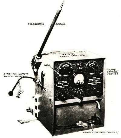
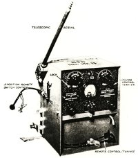
WS No. 108 Mk. II
In the photo above you can see the Bowden Cable for the Off-On-Receive switch, with its attachment strap. It has a push-in clip to hold it in place on the side of the case. Above it is the aerial socket and you can make out the long wire terminal underneath it. Below the remote switch cable are jacks for two sets of headphones and a microphone. The Remote Tuning cable is still clipped into the removable battery cover panel and has its attachment strap neatly folded up. The protruding lug at bottom left rear of the case is part of the back pack frame.
Note: Instead of a Bowden Cable, the WS 108 Mk. I had two leather laces attached at opposite ends of a lever that was coupled to the Send-Receive switch. The operator pulled one lace to transmit and the other one to return to receive.
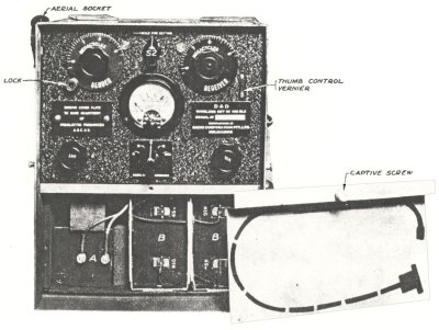
WS No. 108 Mk II. At bottom right is the removable battery cover which
has a stencilled outline of the location for the remote tuning cable.
The batteries (LT "A" and two HT "B") are held in place by a removable front cover which also holds the set in the upper compartment. That cover has a captive screw which when undone allows the batteries to be replaced and the set to slide free of the case. The battery cable and cables for the headsets and microphone were permanently attached and terminated in a socket in the radio compartment so that the set was connected when pushed home into the case.
The remote controls plugged into the set and had canvas straps which could be attached to the operator's webbing at the front so that he had easy access to the controls.
The aerial socket was mounted at 45 degrees so that it did not interfere with the operator in either standing or prone position. A whip aerial extendable up to 6 feet was provided but normally extended only around 3 feet and a long wire could also be connected to a terminal under the aerial socket.
The valve line up was as follows:
V1A 1P5GT (1N5G/1N5GT issued with Mk. I could be replaced
with 1P5GT) Tuned RF amplifier
V1B 1P5GT
1st IF amplifier
V1C 1P5GT
2nd IF amplifier
V2A 1A7GT (1A7G issued in some Mk. I could be replaced
with 1A7GT) Frequency changer
V3A 1D8GT
2nd Detector
V4A 1Q5GT (1A5G issued in Mk. I for V4A could be replaced
with 1Q5GT) RF Oscillator
V4B 1Q5GT
Power amplifier
Although the general design was similar, the front end circuitry of each
set is very different, to account for the different frequency ranges and
different IF frequency.
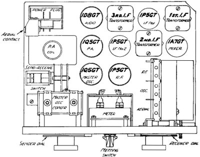
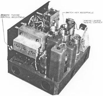
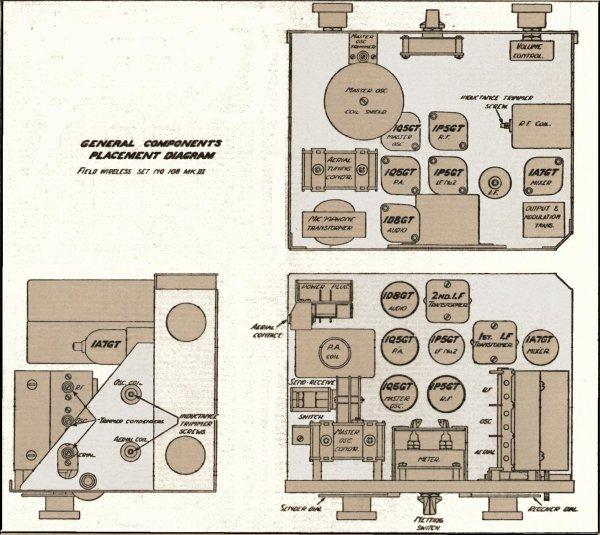
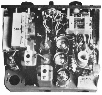
WS No. 108 Mk. II LAYOUT. The Mk. I used different valves
but they could be replaced by the valves used in the Mk. II
Note the battery plug at top left, the spring loaded aerial contact
below it and then at the middle left is the Off-Send-Receive switch
that is operated remotely via a Bowden cable on the Mk. II and a
lever and straps on the Mk. I.
|
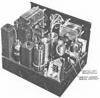
|
| RIGHT-REAR VIEW OF WS No. 108 Mk II | LEFT-REAR VIEW OF WS No. 108 Mk II.
At bottom right is the battery plug |
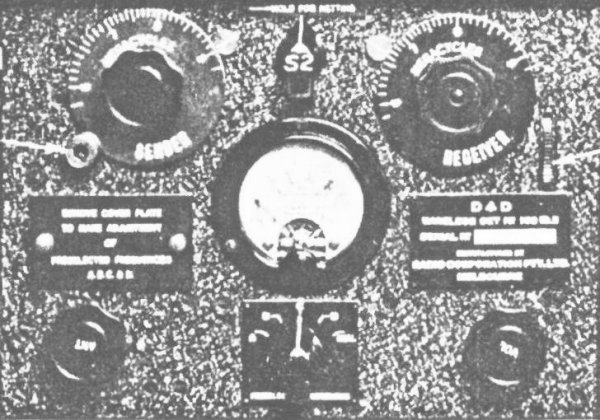
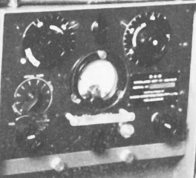
FRONT PANEL OF WS No. 108 Mk II.
Mk I has the same layout.
The differences are the frequency dial markings and the nameplate.
The controls were, from top left:
SENDER Tuning dial with a dial lock at bottom left corner and the
frequency indicator pointer at top right.
NETTING Switch (marked S2) which was held to the left during netting
- "HOLD FOR NETTING". It was spring loaded to return to normal.
RECEIVER Tuning dial with the frequency indicator pointer at top
left and a vernier control thumbwheel at the lower right.
COVER PLATE which was removed for making preset frequency
adjustments.
METER used for dipping the transmitter tuning.
NAME PLATE which had D^D (for Department of Defence), WIRELESS
SET No.108 MK I (or MK II), SERIAL No., MANUFACTURED BY RADIO CORPORATION
PTY. LTD., MELBOURNE
ANTENNA Tuning knob which rotated two turns across the full range.
PRESET FREQUENCY Switch marked A-B-C-D-DIAL.
VOLUME control knob.
|
|
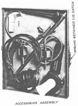
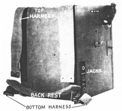
| WS No. 108 Mk I removable front lid containing the headphones, microphone No. 3, telescopic antenna, and Bowden cable for send-receive switching. | WS No. 108 Mk I showing back pack harness and padded back rest. Also indicated are the jacks for microphone and two headsets. Note that the whip aerial mount is at the front of the case. |
The WS No. 108 had a mixed reputation in the Pacific area. When it worked it worked well but it seems that failures were common. In addition the range in jungle was limited (but that would apply to any set). It was used as a coast watchers set when available because it was relatively small and light. The disadvantage was that it needed a guaranteed supply of dry batteries.
WS No. 108 Mk. III
The Mk. III was a development of the Mk. II and looked similar. However the battery was now a single multi-voltage block providing 99V HT and 1.5V LT and instead of spring terminals the battery had a multi-pin socket. The power input to the final valve was 0.5 to 0.6 watts, depending on frequency and length of the aerial. It could operate on voice and MCW and the frequency range of 2.5 Mc/s to 3.5 Mc/s enabled it to communicate with the No. 19, No. 109, No. 22 and No. 133 sets.
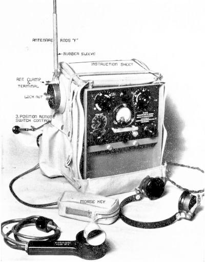
WS No. 108 Mk. III in canvas bag with accessories.
The data on the sets is as follows:
| SENDING (ma.) | RECEIVING (ma.) |
| LT | HT | LT | HT | |
| 108 Mk. III | 310 | 19 | 250 | 10 |
| WEIGHT (lbs) | LENGTH (in.) | WIDTH (in.) | HEIGHT (in.) | |
| 108 Mk. III | 29 | 9 1/2 | 8 | 12 |
The complete station with all accessories weighed 40 lbs.
More attention was given to the aerial system in the Mk. III and a 10 position aerial coil tap switch was incorporated. Positions 1 to 10 were for long wires and 9 and 10 for rod antennae. The set was equipped with aerials as follows:
Antennae Rod "B" qty. 10
(inc. 1 as a spare) Each rod was identical and 12" long and made up 8 ft.
4".
Antennae Rod "F" Each rod "F" was 4
ft long and could be made up as 4 ft., 8ft., 12ft. and 16 ft.
No.1 (Bottom section) qty. 2
No.2 (Middle section) qty. 2
No.3 (Top section) qty. 2
Aerials, 67 feet qty. 1 A rubber insulated
flex wound in figure 8 on a wood dowel with a hook and pin.
Lead: Counterpoise 108 qty. 1 Another 67 ft. length of rubber
insulated flex which could also be used as an aerial.
Insulator W.T. No.1D (Aust.) qty. 2 75 ft. of strong cord with a
weight and insulator attached and used for slinging
aerial,
67 ft. over trees etc. A spare was included.
Whereas the aerial connector on the Mk. I and II was fixed at a 45 deg. angle (away from the operator) the aerial connector for the Mk. III was rotatable through 180 deg. and could be locked in any convenient position with a wing nut. The rod aerial was also secured by a wing nut that doubled as a terminal for the long wire. An earth terminal for the counterpoise was added to the front of the set.
To make room for the aerial tap switch, the previous pre-set frequency adjusting set up was deleted. To accommodate the Voice- MCW facility the preset frequency switch of the Mk. I and II was replaced by an MCW-R/T switch.
The valve line up was as follows:
V1A 1P5GT (1N5G/1N5GT issued with Mk. I could be replaced
with 1P5GT) Tuned RF amplifier
V1B 1P5GT
1st IF amplifier
V2A 1A7GT (1A7G issued in some Mk. I could be replaced
with 1A7GT) Frequency changer
V3A 1D8GT
2nd Detector
V4A 1Q5GT (1A5G issued in Mk. I for V4A could be replaced
with 1Q5GT) RF Oscillator
V4B 1Q5GT
Power amplifier
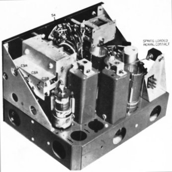
WS No. 108 Mk. III.
Note the missing IF valve and Transformer at top right of above chassis
view.
Note that the Mk. III only had one IF stage whereas the Mk. I and II had two IF stages.
|
|
| WS No. 108 Mk. III showing where 2nd IF valve and coil were deleted from chassis. | Another view of WS No. 108 Mk. III with the empty 2nd IF locations. |
WS No. 108 Mk. III Front Panel.
The front panel controls were, from top left:
SENDER Tuning dial with a dial lock at bottom left corner and the
frequency indicator pointer at top right.
NETTING Switch which was held to the left during netting. It was
spring loaded to return to normal.
RECEIVER Tuning dial with the frequency indicator pointer at top
left and a vernier control thumbwheel at the lower right.
AERIAL TAPS switch with 10 positions, 2 for rod antenna and 8 for
long wires.
METER used for dipping the transmitter tuning. A perspex cover with
clips was fitted to protect the meter.
NAME PLATE which has D^D (for Department of Defence), WIRELESS
SET No. 108 MK III, SERIAL No., MANUFACTURED BY RADIO CORPORATION PTY. LTD.,
MELBOURNE
ANTENNA Tuning knob which rotates two turns across the full range.
R/T-MCW Switch.
WITHDRAWAL BAR. A metal strip on pillars was fitted above the switch
to aid in pulling the set out of its case.
EARTH TERMINAL located to the right of the R/T-MCW switch.
VOLUME control knob.
Note that the battery front cover now had two captive knurled head screws
to hold it in place.
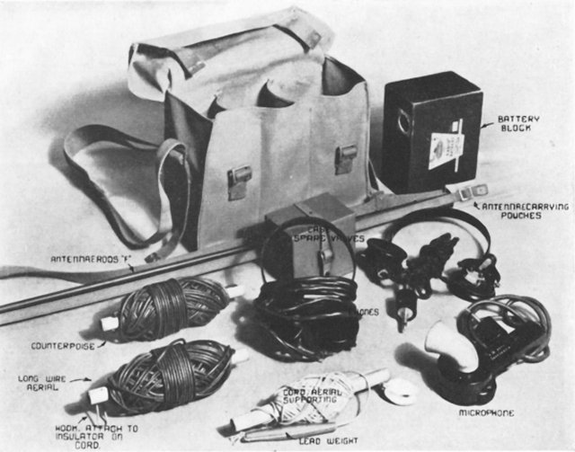
WS No. 108 Mk III Satchel with accessories.
see also my web page on WIRELESS SET No. 208.
References.
Signal Training Volume III, Australian Pamphlet No. 5, Wireless Set No.
108, MKS. I and II, 1941.
Handbook-Provisional (V.A.O.S. No. ZAA8885) for Wireless Set No. 108, MK.
III , 1944
Please note, this article is copyrighted.