
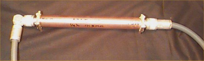
A number of things led me to build one of these. Mainly an abundance of LDF475 hardline and the fact that my yagi's have a folded dipole with a coaxial 4:1 balun this gives me a 75 ohm antenna system right down to the radio. One of these little blighters just before the radio and I'm set.
This was built from the following data
The characteristic impedance of the transformer
is calculated by the square root of the product of the two values to be
matched. In this case matching 50 and 75 ohms
comes out to 61.2ohms.
The hard bit is finding a combination of inner
and outer conductors that gives rise to the impedance needed. After
tabulating a spreadsheed with metric and imperial
precision brass stock as well as hard drawn copper pipe I came up
with only one truly workable pair of dimensions
that gave the apropriate impedance and usable physical properties.
With 7/8 OD hard drawn copper with an ID of 19.83mm
as the outer conductor and the 9/32 OD precision brass tube
which is 7.14mm OD as the inner conductor I came
up with exactly 61.2 ohms.
The characteristic impedance of a coaxial transmission
line can be calculated by Z=138*Log10(D/d) assuming the dielectric
is air
The first step is to solder a 1/4 slug of brass onto the end of the connector. With the aid of a Time Domain reflectometer I positioned the slug and tube so that the impedance transition from the connector to the Transmission line was smooth. the slug needed to be 3mm from the connector's insulating material. This dimension may be different for some connectors but it's fine unless you are up in the High-Ghz area.
The Brass slug is 10mm long and drilled out to
be a snug fit over the connector.
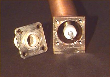
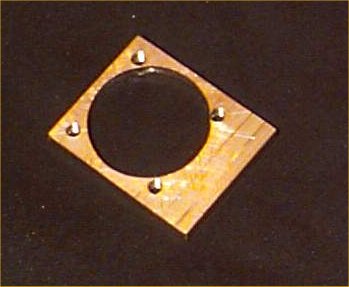 The
end plates were made from 5mm brass plate and drilled out using a step
drill. The mounting holes for the connector are close to the edge of the
large hole but that's ok if you are carefull with the drilling. These can
be soft soldered or silver soldered. Make the outer tube longer than needed
by at least 2 inches so that a pipe cutter will work properly. It is difficult
to get a nice right angle using a hacksaw but possible if you take your
time. Using a lathe will work fine too.
The
end plates were made from 5mm brass plate and drilled out using a step
drill. The mounting holes for the connector are close to the edge of the
large hole but that's ok if you are carefull with the drilling. These can
be soft soldered or silver soldered. Make the outer tube longer than needed
by at least 2 inches so that a pipe cutter will work properly. It is difficult
to get a nice right angle using a hacksaw but possible if you take your
time. Using a lathe will work fine too.

Solder only one end plate on and tap the mounting
holes if you haven't already done so.
I used 3mm screws.
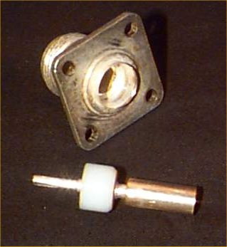
Press the center out of the second connector using
a piece of copper tube in a drill press. The copper pipe needs to clear
the inner conductor and meet the insulating material. Most of these connectors
are held together by a lip on the back that is lightly swaged over the
insulator. After removing the inner part soldere a 1/4" slug onto
it the same as the first connector. Clean out the swaged lip on the connector
shell with a reamer so that the inner section slides in easily but not
too loose.

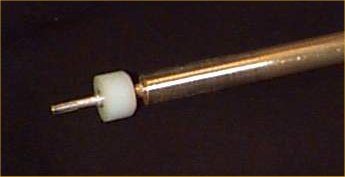
work out a quarter wave length in air for the
center frequency required and cut the 9/32 brass tube to that length. solder
it onto the 1/4 brass slug's ensuring that it covers the slugs completely.
My Wavelength
calculator program is great for this sort
of job
Now for the exacting bit that really matters. Push the connector shell over it's inner components and measure the distance between the two flat's of the connectors. This is the length that the outer tube needs to be. If the outer tube is too long the second connector inner portion will be too far back in the connector. If it is too short there will be too much load on the inner section when you screw it together. Just be exact or make it too long by a mm or so and then file the end down untill it is ok. at this point you can solder the other end piece on.
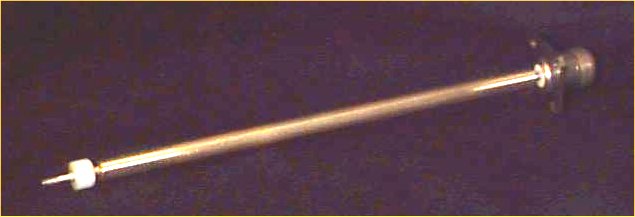
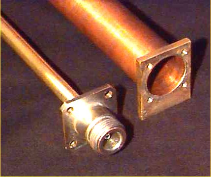
The inner portion can then be installed
along with connector 1 leaving you with just the outer portion of connector
2 to slide on and screw down.
![]()
This Information is provided by Kerry Richens VK1TKR in the pursuit of Amaetur Radio and the free exchange knowledge and ideas.