An RS485 network up the Mast!
Another Bleeding edge project
page
![]()
Well, Here it is schematics and all free of charge but all Copyrighted so that
there is no commercial use allowed.
This project capitalises on the wastefull nature of society as a whole and demonstrates
that one can be a Junk Box Homebrewer
and still end up with a professional finnish. Just remember that in all of this,
You only get what you give. If you do a crappy job it will be a crappy station
The best thing to do at this point is to have a close look at the following picture to understand what this is all about. It tells all about what and why.
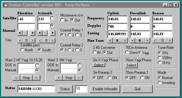
The bits you don't see in this are Winorbit tracking software providing DDE to my program and my program providing mode and tune data to a FRG9600 aas well as a Winradio 1000-I. This happens along with the management of all the commands to drive rotators and relays etc..
Here is a list of goodies that helped my Quest
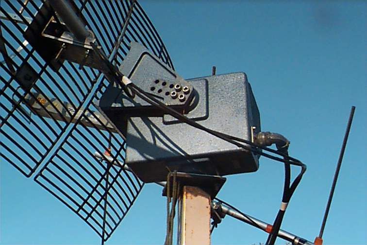
Disgarded Broad Band Lan distribution boxes. They take N type connectors, are cast aluminium and have both compression RF shielding on the seams and Neoprene gaskets for waterproffing.
Large Pan Tilt Heads from Government Surpplus Auctions.
Ex Utility equipment from hamfests such as Coaxial Relays, N Type Terminated cables etc..
You may want to have a browse through my power point presentation that I used at the ONE-Tech 2002 Symposium hosted by The WIA which was organised and run by Peter Ellis (VK1KEP)
![]()
RS232 to RS485 converter for the PC end
The Micro boards used in all of the following projects
Modified Hills rotator on the network
Phasing Harness including 'preamp bypass relay' control
and other goodies
like preamp and downconverter power control
In the Shack Rack remote controller
![]()
Well, If you're going to make all of these networkable devices then you will need to convert the PC's levels from RS232 to RS485. Before we go into that I should discuss the points for going to RS485 rather than another medium.

RS232 to RS485 Schematic
PCB Layout
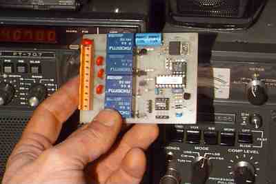
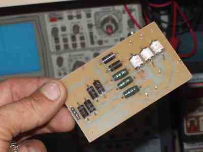
The Chippies I used are the PIC 16F84 and Believe it or not, the Basic Stamp by Parrallax
|
This board features Pic Micro socet takes Basic stamp or Pic-16C/16F series Micros
|
 |
|
This board features Pic Micro socet takes Basic stamp or Pic-16C/16F series Micros
|
 |
Wow what an amazing ammount of work can be acchieved with such a tiny processor. I speak of the PIC16F84 and such like. In this project I haveconstructed a dual axis rotator control that is controlled via an RS485 network. Here are the project spec's
1. networked
2. no calibration Pots' anywhere
3. Software calibration
4. either 2 or 3 Chips depending on wether you us the Stamp Basic or My compiled
version
5. Serial commands are 'Plain Language' eg: "#10g300,45" means Device
10 go to 300 azimuth by 45 elevation
6. The PCB design is small and easy to construct
The Pic micro measures the position of both axes by discharging
a capacitor through a potentiometer attached to the maain shafts.
The micro toggles the I/O pin between being a Schmitt triggered input and being
an output pin being actively driven low. The toggling happens very fast 100uS
cycle. When the shmitt input goes low, the number of cycles used to discarge
it is recorded as a 16 bit number.
The next super cool thing is that a second order polynomial
is used to linearise the partial exponential curve generated by the pot's
range of adjustment. The calibration numbers are stored in EEPROM within the
micro and Voila!! you have a measurement that is good to about 2 degrees without
the use of any ADC.
I hear you say 2 degrees is prety crappy. Well it's darn good for the sorts of antenna I am using at the moment. I do intend to make a much more precise version but it's not going to be as simple as this one by a long shot
Wiring Diagram
PCB used Layout
PCB Schematic
Firmware
Diagnostic and Calibration Firmware
|
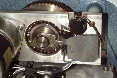
This May look a little small, but it is a very robust little unit. It is in fact a surplus Pan/Tilt head for a large external camera housing. I have installed 10 Turn potentiometers on each axis. The Pot's are monitored by A PIC16F84 Micro.
|
 |
|
Limit switches are always a great idea in preventing a buildup of brass gear teeth at the botom of the case(Never trust a micro). You can see the 10 turn pot installed and directly geared to the main shaft |
 |
 |
 |
 |
|
![]()
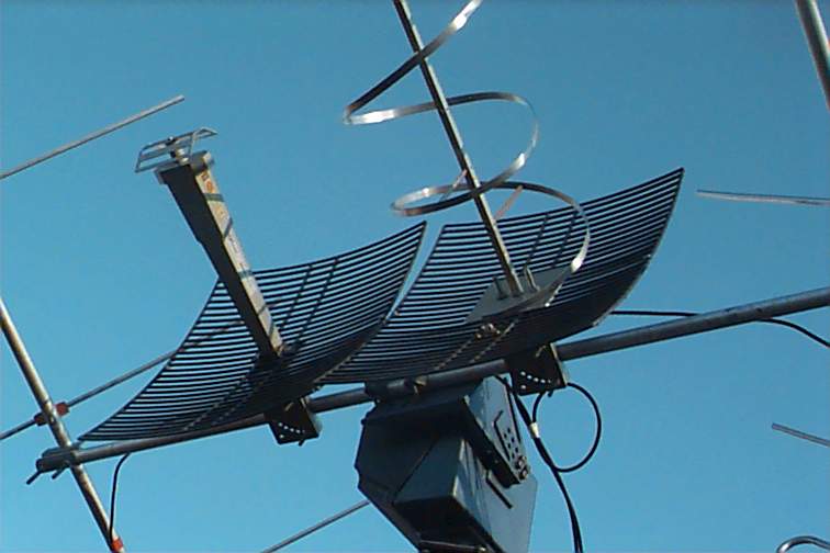
Here's the cool bit. You can install the controller in an existing
rotator to get it on the network. You remember those domestic
Hills, Radiospares (Tandy) rotators that a great many hams used for their 2
meter yagis etc.. They had a little switch in them that synchronised
the control box with a solenoid. Throw the control box away and daisychain all
of your masts on the one control cable
|
This box was a Distribution amplifier for Broad Band Lan. It was rescued from the metal recycling yard for $2.00 It now houses the Power inserter for the 2.4Ghz downconverter |
 |
|
 |
![]()
|
Here is a MIL spec coaxial relay. These little units are Frightfully expensive at the best of times even though they used a 110Volt AC motor in them. To make them more usefull for remote switching, the motor was replaced by a 12 volt DC motor and the obligatory Micro controller board to make it a network addressable device |
 |
| What a neat job. Anyone can homebrew, Just spend the time to make neat brackets etc.. |  |
|
Heres another old Broadband Lan diecast box with neoprene gaskets and RF screen bead on the seams. These are splitter boxes for Aluminium Hardline. The cool bit is that the ports are the same thread as a N-Type connector.
|
 |
|
Theres just enough room for the Coaxial Relay,connectors and Microcoltroller board. Note that the Micro board is only populated with one driver transistor unlike the picture below |
 |
PCB Layout
Schematic
![]()