Have you ever wondered what to do with some of those old vacuum tubes you've gathered over the years? Why not bring them to life and put them on-the-air!
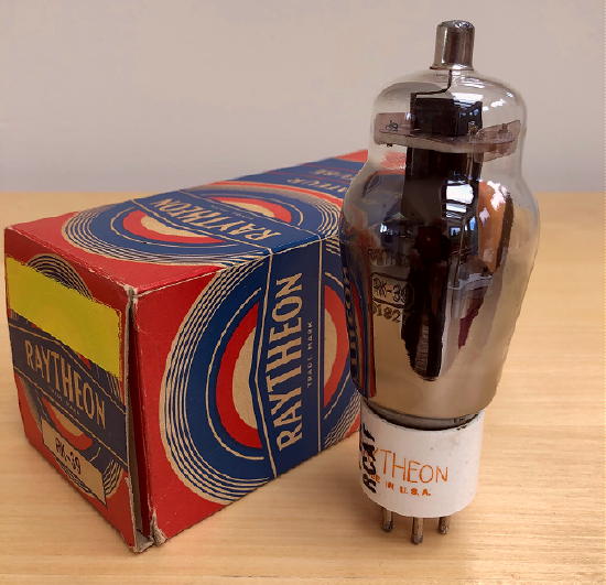
About twenty years ago, Ralph (VE7XF), gave me several RK-39 tubes. The tubes were in their original boxes and after inspection, appeared to have originally been supplied to the RCAF, perhaps eventually ending up in amateur radio use. One of the boxes indicated 'fair' while another was marked 'ng'. The tubes, probably manufactured in the 40s, came in very colourful boxes, typical of what was often produced in the golden years of vacuum tube technology.
Descriptions of the 'new RK-39 first appeared in early 1937 radio magazines and from what I can tell, manufacturing likely started around the end of 1936. A similar tube had also just found its way into the market, a tad earlier, and this was the 807 from RCA. The 807 was a cleaned-up version of the already popular 6L6, with a few changes to make it more appealing for RF-service rather than for audio.
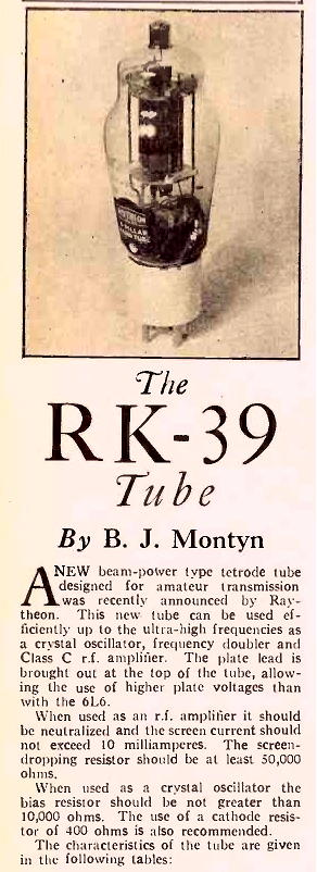
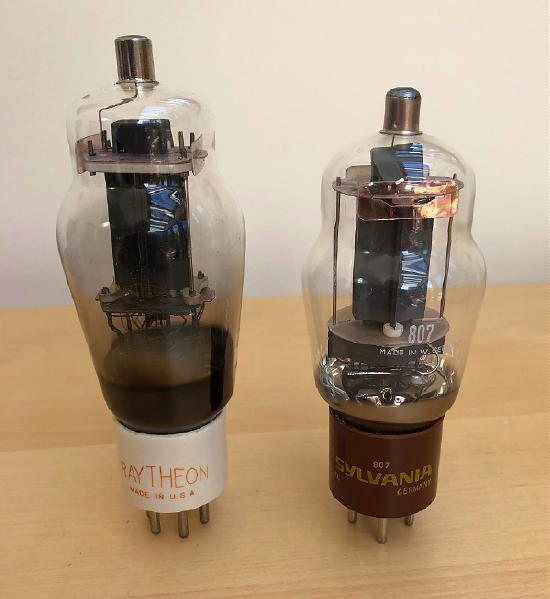
The RK-39 was Raytheon's version of the 807 and had a slightly different architecture ... a little more robust but a bit harder to tame in RF service. Both tubes were of the new 'beam power tetrode' design, using separate electron-stream beam-forming plates to reduce secondary emission. Physically, both tubes were similar in appearance, with the RK-39 being a bit larger. Both tubes came with a grand-looking white ceramic base but standard 807s quickly switched to the more familiar brown Bakelite bottom.
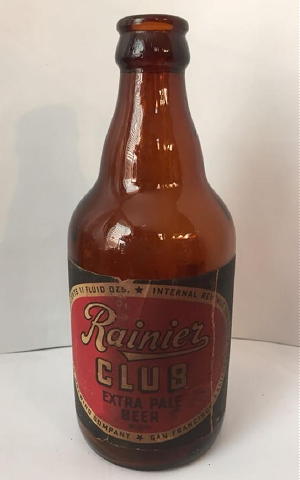
It wasn't long before the better-shielded, less finicky 807, grew in popularity, leaving the RK-39 to lose favour with the amateur radio crowd but still find popularity in commercial and military gear of the day. In many circuits, specs called for either the RK-39 or the 807 as they were usually interchangeable ... but hams soon fell in love with the 807 and for the next three decades, until the 6146 knocked it from its perch, the 807 could be found in hamshacks around the world. Even today, because of its shapely resemblance, hams fondly refer to a cold beer as an '807' !
'807'
Over the years I have pondered some way of putting these glorious-looking old RK-39s to use rather than having them sit quietly in their boxes, gathering dust. What might a typical ham in 1937 do with their newly acquired RK-39 or 807?Certainly one of the most popular transmitters of the 30s and not overly difficult to build, was the single-tube crystal-controlled power oscillator. Having built a few 6L6 / 6V6 power oscillators that worked very well, always providing 8-10 watts of reliable output, I thought that this might be a probable choice among hams of the day. These newer tubes had the potential to produce a bit more power than their predecessors and for DX-craved hams in the 30s, gaining a few more watts without breaking the budget meant more QSLs on the wall!
There were a few tried and true generic circuits in the 30's Handbooks that looked interesting, including the Tri-Tet oscillator. While building a Tri-Tet for 10-20m using a 6L6, I had tried the RK-39 as well as the 807 in this configuration. I found both tubes to be very unpredictable and somewhat unstable when quadrupling to 10m. I later discovered a few articles from the 30s that suggested these tubes would be poor choices for a Tri-Tet.
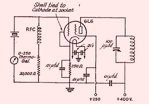
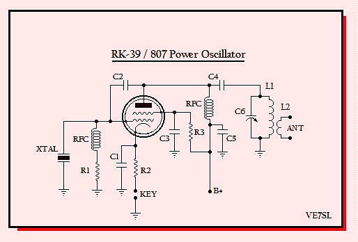
The standard tetrode grid-plate oscillator appeared to be a good option and the circuit that I chose to duplicate was a generic one, found in most of the early Handbooks. With this in mind, I went about optimizing the circuit for my RK-39.
During the test bed mock-up, enough good performance was realized to proceed with the final construction. Power output was sufficient (~12W) to guarantee good solid contacts and keying was surprisingly good.
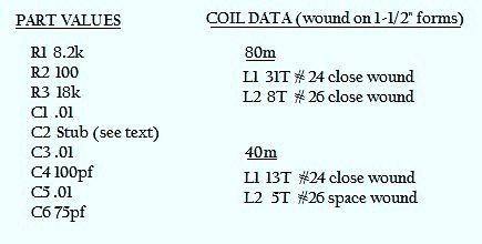
As noted in the manufacturer's specs, using the RK-39 as a crystal oscillator would probably require a bit more grid-plate coupling and they suggested around 2pf would be adequate. I eventually employed a short wire stub running from the tube's control grid to up near the plate.The final test bed part-values that offered best performance with my RK-39 are shown below.
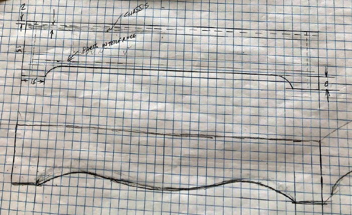
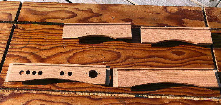
Once optimized, final construction began by first playing with possible part locations as well as final appearance. I decided that rather than an aluminum chassis, the rig would be built on a solid aluminum plate and supported in a small wood frame.
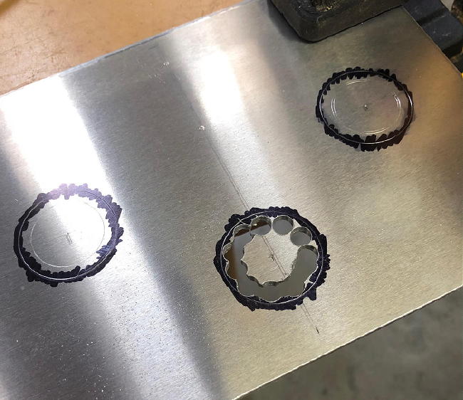
The 1/8 inch thick plate was drilled out for the tube sockets and hand-filed to size.
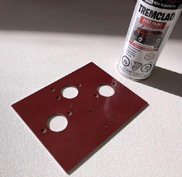
Once all of the holes were drilled, the plate was spray painted and slow-baked in the kitchen toaster oven. This is best done while the XYL is not around.
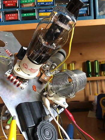
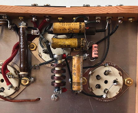
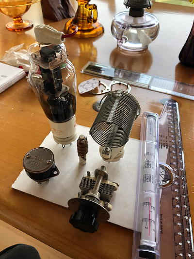
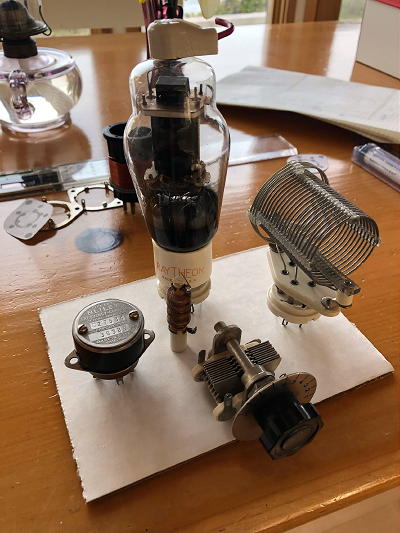
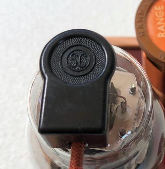
Since I was emulating a '37- style rig, all components were from this era or could have been found in a junk-box of the day. This even included a vintage Stromberg-Carlson Bakelite plate cap for the tube. As usual, the bypass capacitors are vintage wax caps that were restuffed with modern ones.
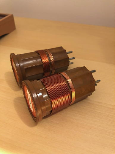
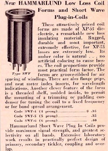
The eighty-year-old Hammarlund coil forms, once riddled with holes from long-gone coil windings, were filled, waxed and polished, before winding a pair of 'new' 40 / 80m coils. These were just 35 cents in 1936 which is about $6.50 in today's money ... which I would be happy to pay if they were still available!
A frame for the chassis was cut from leftover Douglas Fir cuttings then sanded and given several coats of satin polyurethane varnish before final assembly.
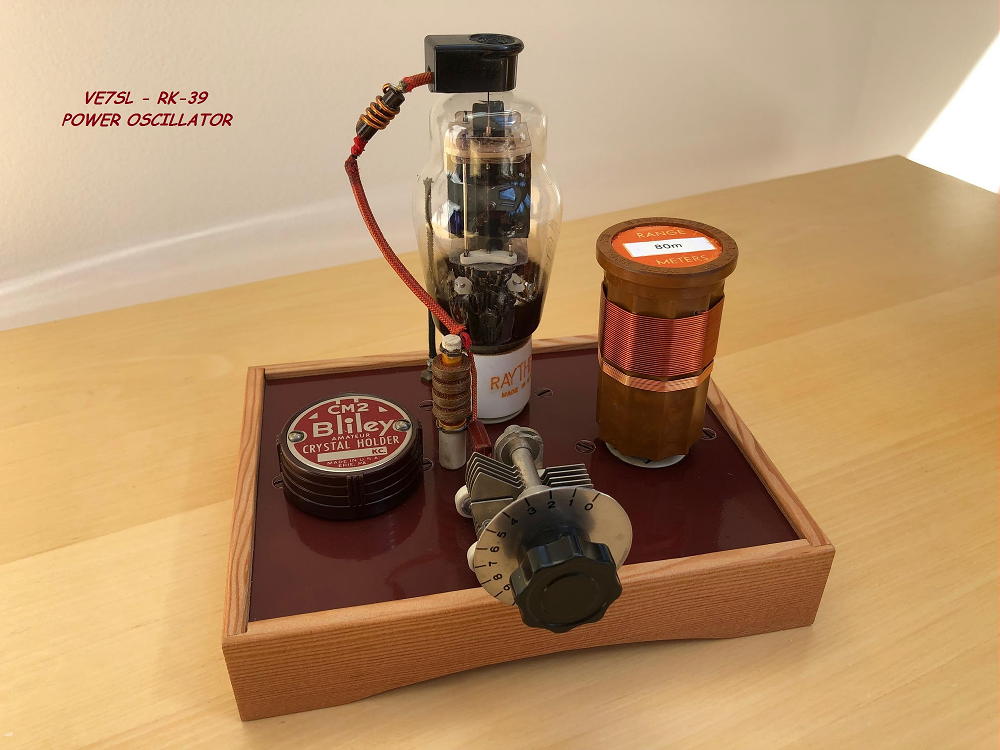
The finished transmitter matched my initial visualization and its actual performance improved somewhat compared to the original test bed version with its numerous clip leads and less attention to parts placement and lead lengths.
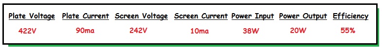
The measured operating parameters are shown below. Possibly because of the RK-39 and 807's 'beam-forming' plates, plate efficiency of the circuit is higher than what I usually see with crystal power oscillators:
As always, with a link-coupled output into a 50-ohm antenna system, a few extra watts will be gleaned by tuning the output link with some series-capacitance. You will see a definite peak in output power when the correct tuning point has been found.As previously mentioned, the RK-39 (and the 807 to a lesser extent) will benefit from some additional grid-plate capacitance to increase oscillator feedback and to encourage reliable crystal start-up. This was done by mounting a short stub from the control grid, alongside the tube's plate. The greater the coupling, the stronger the oscillation becomes but too much feedback risks fracturing the crystal.
The oscillator keys nicely with most crystals except the large FT-117B slabs, designed for the BC-610. Perhaps they require even more feedback still or they may be of a different cut, not suitable for this particular circuit. Even small HC-49 crystals will key in this circuit without cracking, but not surprisingly, do tend to chirp somewhat! Output loading also affects the keying quality, with heavy loading being better ... probably because this lowers R.F. crystal current.
One change that I always like to make when using circuits from the 30s is to make them less lethal to the operator. One only needs to thumb through any QSTs of the day to read of the regular electrocution of radio amateurs while operating or adjusting their transmitters. With the addition of a plate blocking capacitor, the circuit was changed from series-fed B+ to shunt feed, which removes the high voltage from the plate tuning capacitor as well as from the plug-in coil. This should ensure no late-night sleepy surprises, when changing coils.
Over the past few nights of summer-time testing, I've worked several western-state stations with the RK-39 and have easily heard my signal via online SDRs in Iceland, Brazil and along the east coast, while CQing on 40m.
I usually operate my crystal-controlled rigs on 3550 or 7120, so if you hear me, please give me a call!