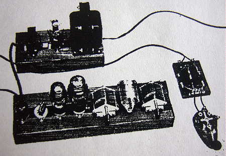
The 'Longfeller' transmitter was brought to my attention in 2009, by Tom Hamblin, VA3HN. 'HN' had been operating a slightly modified version of the transmitter which was based on an article originally published in the July 1946 issue of QST. In "A Beginner's Two-Stage Transmitter" by David Middelton (W2OEN), the author described a simple two-tube CW transmitter designed for the 80 and 40m bands. The circuit used two 6V6 tubes - - one as an untuned crystal controlled Pierce Oscillator (very popular in the 30's and 40's) and the other as a simple Class-C final amplifier. Built on either a narrow slat wood frame or on a narrow aluminum chassis, the built-in power supply and in-line tube arrangement presented a rather unique-looking and somewhat 'longer than normal' transmitter. The original wood-based Longfeller was just 4" wide and 15" long and was well-deserving of it's folksy nickname. After several attempts to work 'HN' on 80m CW, we were finally successful, and I was able to hear his Longfeller in action. It was then that I put the Longfeller on my 'must build' list, if for no other reason than to be able to say, "Rig here is a homebrew Longfeller!" ....what follows is a description of the very enjoyable project.
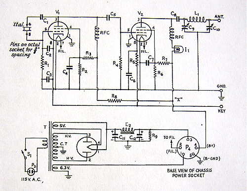
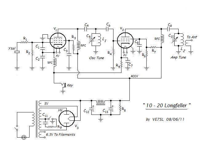
As shown below, Middelton's original circuit used a 6V6 crystal-controlled Pierce Oscillator with an untuned output stage. Although capable of providing ample drive to the amplifier on both 80 and 40m, the Pierce also had a bad reputation as a 'crystal-cracker' because of the higher than desirable RF current through the crystal. These days, good crystals are precious and not nearly as plentiful as they once were. The thought of destroying one was not something I wanted to even consider. I decided that I would need to experiment with at least a couple of different oscillator circuits and see how they performed. Unlike Middelton, one of my major goals was to be able to put my Longfeller on the 'ultra-highs' of 20, 15 and 10m CW! Just a few watts on 10m during the peak sunspot years can provide many hours of DX enjoyment. If I could realize at least a couple of watts from my Longfeller on 10m, I would consider it a success.
The first task was to build up a small test-bed in order to compare oscillators as well as to optimize part values for both stages. The original 6V6 Pierce was changed to a Modified Pierce, using a tuned plate circuit and the vastly superior 6AG7. It is not surprising that Middelton did not choose the 6AG7 for his oscillator as it was only around this time period that others were beginning to notice the excellent performance to be had from this great little tube. This was later confirmed in a QST classic by Vernon Chambers (W1JEQ) in the March 1950 QST article, 'Crystal-Controlled Oscillators - A Review of Modern Crystals, Circuits and Tubes'. The Modified Pierce closely resembles the typical grid-plate crystal oscillator but is vastly more 'crystal-friendly' than the original design.
The Modified Pierce with tuned output proved to be a fairly good performer. As in most grid-plate oscillators using a tuned output stage, the keying characteristics of the crystal were somewhat dependent on output tuning. The Modified Pierce was capable of providing good output when doubling from 40m, and keying with most crystals was certainly acceptable, once properly tuned. However, not all of my crystals would oscillate using this circuit and some of them keyed sluggishly no matter how the output tuning was adjusted.
Next on the oscillator- list was one recommended in Bill Orr's Radio Handbook, the Harmonic Colpitts Oscillator. This circuit proved to be a true delight as it provided excellent output when tuned on both the fundamental as well as on the crystal harmonics...not surprising in view of its name. Crystals that would not even oscillate in the previous circuit keyed easily and the characteristics of the note were not affected at all by tuning the output. The shielding architecture of the 6AG7 is evidently taken full-advantage of with the Colpitts design. Although regulation of the screen voltage was tested with both circuits, there appeared to be no discernible improvement to be gained by doing so.
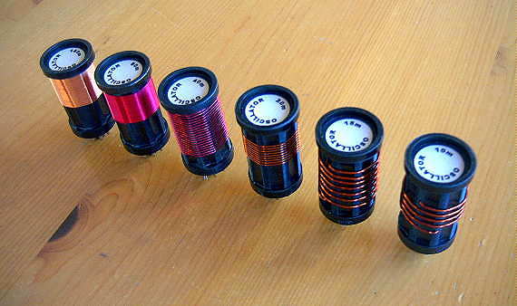
There were no significant changes made in the final amplifier circuitry or in the power supply other than to change the output tank circuit from a pi-network style to a parallel tuned L/C link-coupled tank so that I could utilize a set of B&W JEL style plug-in coils. The coils would allow me to tune the final amplifier on all bands from 160-10m.
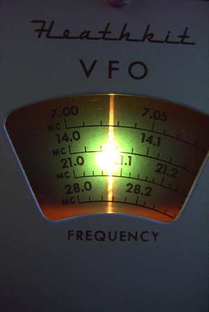
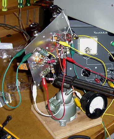
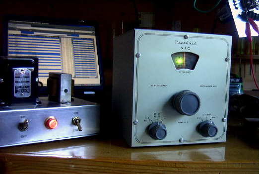
It was during this 'haywire' bench testing phase that I was able to make some power measurements and experiment with coupling a VFO into the Colpitts oscillator while using it as a buffer stage. As it turned out, the circuit worked just fine with no changes, allowing the VFO output to be plugged directly into the crystal socket with no switching required. Using the venerable Heathkit VF-1, drive levels were at the same level as those produced when using a crystal. While bench testing the rig mounted in the vise, I tuned to 10m to check the keying quality, which seemed excellent. I also noticed that the band was 'open' and that there were many Field Day stations on the low end of 10m CW. I plugged an antenna into the test bed and worked several W1's, 2's and 3's on the east coast, including W1AW. Having a QSO with W1AW somehow seemed appropriate for my QST-based building inspiration!
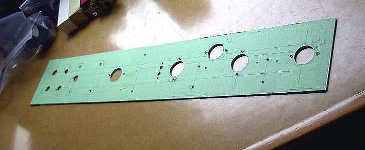
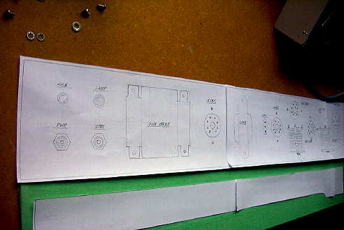
FINAL CONSTRUCTIONOnce all testing on the lash-up model was complete, a full-sized drawing of the intended layout was made as well as a plan for the wood base-frame.
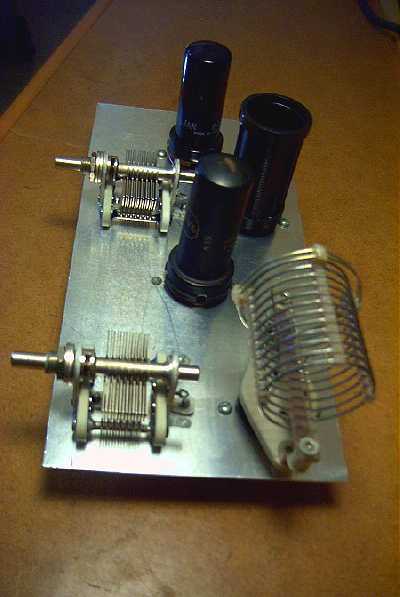
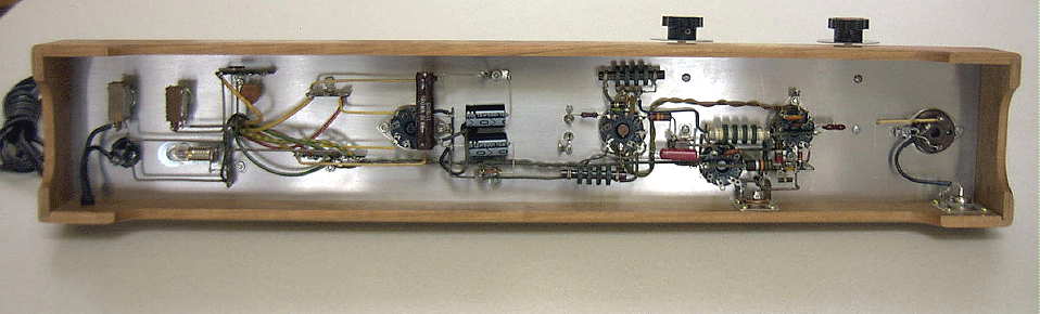
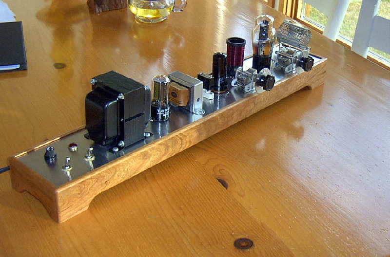
The 1/8" aluminum plate was taped to prevent any scratching during construction. Since the plate was too thick for my chassis punches, each socket hole had to be drilled out along the inside edge with a series of holes and then filed to shape. All of the sockets, and almost all of the components are recycled parts from many years of building a junk-box.
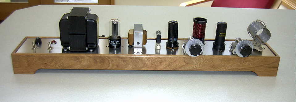
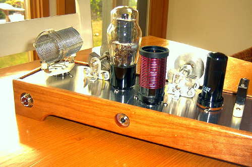
The completed transmitter and frame turned out as visualized and thanks to the pre-built shakedown model, fired-up without any surprises.
The coaxial antenna socket and key jack were brought out on the back side.
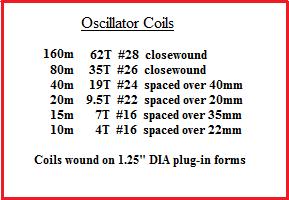
The '10-20 Longfeller' is capable of operating from 160m through 10m using various combinations of crystal or VFO input frequencies as well as various combinations of oscillator / amplifier configurations. A set of oscillator plug-in coils allows the 6AG7's plate circuit to be tuned to the crystal fundamental or any of its harmonics which in turn allows the 6V6 final to be used as a doubler or as a 'straight-through' amplifier. The final amplifier appears to be very stable even when it's input and output circuits are tuned to the same frequency. Final amplifier output is very robust, even when doubling, but not surprisingly, is always higher when running straight-through.
In general, the 6V6 output power measured into a 50 ohm load runs about 9W on most bands (depending on whether the final is doubling or running straight-through) down to 8 watts on 10m. Output on both 160 and 80m is 5 watts. Substituting a 6L6 into the final amplifier gives, depending on the band, 2 - 3 watts more output. These figures are the same when running with the VFO as well. Crystal keying of the Colpitts oscillator is exceptionally good although some chirp is evident when operating on 15 or 10m, depending on the particular crystal I am using. It seems that each crystal has a slightly unique keying characteristic and keying both the oscillator and the final quickly reveals the best or the worst of the bunch, particularly on the two highest bands where any crystal sluggishness is multiplied by three and four times respectively. When I was a young teenaged ham in the early 60's, most signals above 20m had this unique but mostly long-gone characteristic.In spite of its stability, there is some indication that the final stage would benefit from some form of neutralization as on both 160 and 80m only, the plate current 'dip' (minimum) does not correspond to the maximum output power. This may account for the lower than expected output power on these two bands. As well, and remaining to be confirmed, I suspect that the antenna output links on the 160m and 80m B & W coils would benefit from a few more turns.
[I was able to confirm this today on both the 160 and 80m coils, with a temporary antenna link winding of 6 turns compared to the original 3-turn link. Power output is now 11 watts on both bands with the 6V6 and 14 watts using a 6L6. It seems that the original 3-turn link is not truly optimized for 50 ohms on both the 160 and 80m coils]
I plan to operate this transmitter a lot during the upcoming solar cycle peak years, especially on the three higher bands. Please give me a call should you hear me and the "Longfeller"!
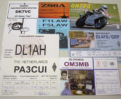
*** Update: During the fall of 2011, I had a chance to use the Longfeller on 10m, during periods of some fantastic propagation to Europe! Calling CQ on one frequency, I was able to work over 100 European stations, along with a wonderful contact with ZS6A in South Africa,
who reported the exciting QSO in his radio BLOG here along with further comments here.
QSL cards from those nice openings are beginning to arrive here now, via the QSL bureau. ***