BUILDING A CLASSIC - THE 'HULL HARTLEY' TRANSMITTER
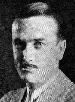
Ross Hull was the Associate Editor of QST magazine from 1931 until 1938. By all standards, Hull was a technical genius and prolific author. Originally from Australia, Hull moved to Connecticut where he soon developed a reputation as a tireless builder and experimenter. Although Hull's main interest leaned towards the development of radio-controlled aircraft, his well-documented investigations into the field of VHF tropospheric propagation led to several major discoveries of what we now take for granted. Always pushing the boundaries of new technology, Hull's life was cut short at age 36 when he was accidently electrocuted while demonstrating his recently built television receiver to a friend. One can only imagine the many additional contributions Hull might have made to the technical world had his life not ended so soon. More on the life of Ross Hull can be found here..
In 1928, Hull penned a QST article which soon became a classic - "Overhauling the Transmitter for 1929". The article discussed the need for amateurs to clean-up their signals for the upcoming new regulations governing frequency control and stability. Hull demonstrated that even a simple breadboard transmitter could meet the challenge by simply paying more attention to operating parameters, proper tuning and good solid construction techniques. Hull's 'Hartley Oscillator', referenced in the article, is the basis for my construction project described below. A link to Hull's 1928 article can be found here.
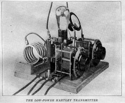
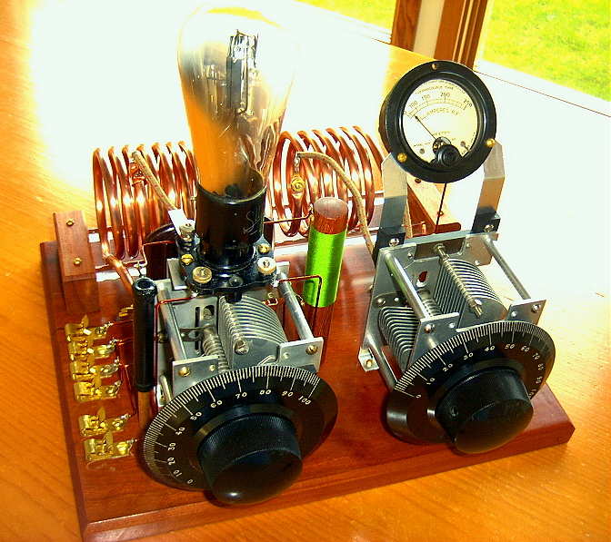
When I first read Hull's article several years ago, I was struck by the unique appearance of his transmitter's design. With many of the components strapped tightly to the back of the plate capacitor and the tube socket mounted on the top, it struck me as the perfect example of 'form following function'. Hull's genius of component placement makes it appear as if the National DX capacitors were made exclusively for this circuit! The symmetrical capacitor placements, along with their respective National Velvet Vernier dials, resulted in a radio whose eye-appeal has stood the test of time. Looking at the transmitter today, nothing screams "1929 radio" more than this one, yet at the time it represented basic state-of-the art for amateur radio!Although Hull's circuit could be duplicated using a variety of available capacitor styles, it would be almost impossible to reproduce the exact appearance without utilizing the uniquely constructed National DX variables. Once again, Lou (VE3AWA) offered his enthusiastic support for my project and sent me two of these old gems. A year earlier, Johnny (KE7V), knowing of my interest in vintage radio construction, had sent me a pair of National Velvet Verniers for use in a 'future project'. Without the generosity of these two amateurs, this project would still be on the drawing board.
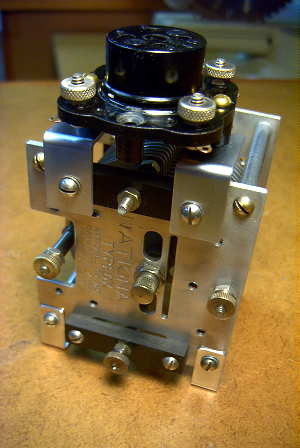
Construction is centered around the hallmark feature of Hull's layout - the high-mounted tube socket, firmly strapped to the top of the plate tuning capacitor. Placing the tube socket well out in the open not only allowed for short connections between the tube and vital components but also allowed the tube to quickly radiate any developed heat.This photo also illustrates the unique construction of the National variables, with separate stator and rotor connections available on either side as well as on the top and bottom, unlike most variables that bring these connectors out at the sides.
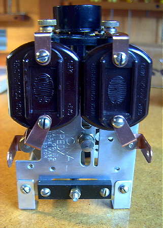
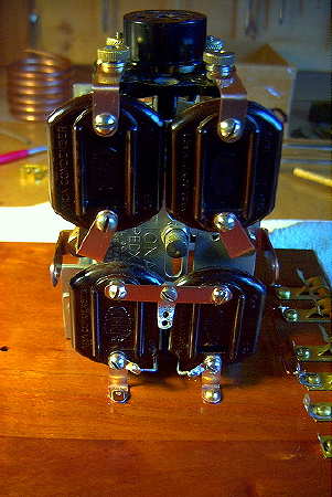
Hull was able to take advantage of the DX cap's unique construction by fabricating short low inductance straps to support the plate blocking capacitor and the grid capacitor, both Sangamo micas, as shown above. He maintained the symmetrical layout by mounting the filament bypass capacitors, also Sangamos, directly beneath the top pair.
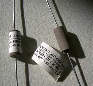
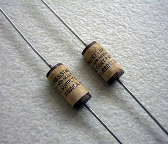
The pictures from the originlal article are not clear enough to determine what Hull used for the center-tapped filament resistor. It seems as though it was placed under the plate capacitor and out of sight. I manufactured a pair of old-looking filament resistors by sanding the color bands from a pair of 47 ohm resistors and attaching a computer printed label. Once glued in place, the label was stained slightly so that it didn't look too new. I don't believe that Lavite ever produced resistors that looked like this but since they were not going to be visible beneath the capacitor, I was content with the final outcome.
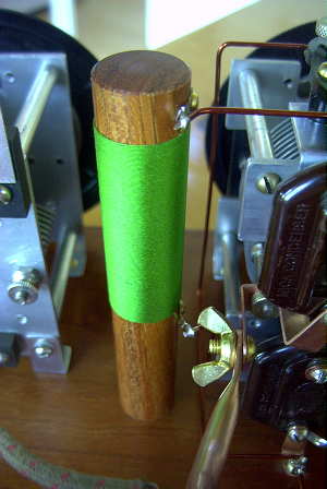
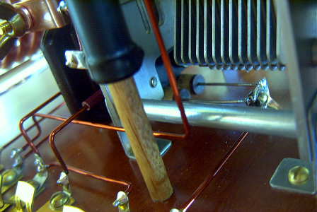
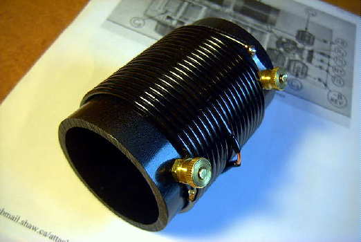
The RF choke, hand-wound on a 3/4" turned Cherry form, consisted of 160 turns of #31 wire resulting in a measured inductance of 166uH. Not much compared to the typical RF chokes used today but apparently more than adequate for the task. This photo also illustrates the method of fastening the 1/4" copper plate coil to the capacitor. Wing nuts were used, as in the original, to facilitate easy coil changes. This connection must be solid as a large amount of RF current flows in the tank circuit.The bottom part of the wire-wound grid leak can be seen below. As per original plan, it has been mounted on a 1/4" dowel close to the tube socket and grid connection.
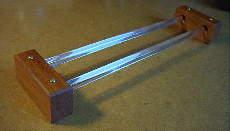
Hull's original design called for two glass towel rods to be used as coil supports for the plate coil and the antenna coil. Unlike the original, I substituted readily available plexiglass rods, supported on two Cherry end blocks.
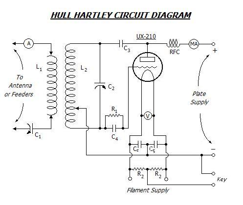
SCHEMATIC & PARTS LIST
The 1/4" copper tank coils are identical to the ones used on the '29 TNT transmitter. All of the coil-winding information can be found on the 1929 TNT Transmitter page.
OPERATING PARAMETERS With the antenna tank coil loosely-coupled (approximately 1.5" space bewteen coils), a plate voltage of 400 VDC produces 32mA of plate current. The measured output power into a 50 ohm load (as well as a properly matched 50 ohm antenna) is 5W, indicating a plate efficiency of 39%...typical of most power oscillators. With close-coupling, the plate current rises to 47mA, with a measured output of 8W and a plate efficiency of 43%. Interestingly, with the loose-coupled antenna tank coil, an additional 330pF of capacitance (in parallel with the 500pf variable) was required to resonate the tank when running into an antenna. With tight-coupling, the tank resonated with the single 500pf variable alone.
The original article makes no mention of the method used to key Hull's transmitter. Since only four Fahnestock clips are shown near the tube, it is probable that Hull keyed the B- line, a scary but not unusual practice at the time. I elected to key the center-tapped filament circuit which required an additional two clips, creating another (yet far safer) departure from the original circuit. The transmitter's CW note is clean and crisp, and by 1929 standards, would be easily described as 'XTAL' quality - more than surpassing Hull's objectives.
160 METERS In preparation for upcoming 160m activity, newly allowed in the yearly Bruce Kelley '29 QSO Party, I wound a set of coils for the Hull Hartley. Both coils were wound with information provided in George Grammer's QST article, "A Low-Power 1715 Kc CW Transmitter" (March 1932), a Hartley oscillator using a 45 triode. Both this design and the Hull Hartley utilize a 500pF plate tuning capacitor and I found the values provided to be spot-on. Unlike Grammer's design, using bare enamelled #12 and a co-wound string for spacing, I used jacketed #14 (Home Depot) and let the PVC jacket take care of the spacing. The plate tank coil form was a 3 1/2" piece of 2" ABS tubing (2 3/8" OD) and was wound with 18T and tapped at 8T from one end; the 2 3/4" long antenna coil was similarly wound with 12T in total. When finished, both coils were given a coating of hi-gloss sealant.
The keying on 160 sounds very good and could readily pass for a more modern rig. You can click here to listen to the on-air signal.
My one and only CQ on 160m was answered by Paul, N1BUG (2500 miles to the east in Maine), who describes our contact as well as posting a few recordings of my signal. It would seem that '29-style 160m transcontinental QSO's should be possible, given good conditions and good 160m antennas at both stations. Hopefully others will be encouraged to wind coil sets for their '29 transmitters and get their feet wet on topband during the next Bruce Kelley '29 QSO Party.