OVERVIEW - This is a description of a broadband ( ~40kHz - 500kHz) shielded receiving loop and preamplifier suitable for low-noise LF reception. The preamplifier was originally developed by the late Ralph Burhans, a dedicated engineer and LF experimenter. The components for the preamp are inexpensive and readily available from Mouser Electronics. The loop is an excellent performer, and is well suited to those interested in 2200m, Lowfer, NDB or LW Broadcast DX work.
CONSTRUCTION -A lightweight method of constructing the loop can be achieved by using a large diameter coaxial cable such as RG-8, RG-11 or rigid hardline. I have built both a six-foot version and an eight-foot version and have found that both sizes will yield good performance, with the edge going to the eight-footer. I don't think there is anything to be gained by going larger.
If you are using rigid hardline coax, you should be able to support the loop with a single vertical mast. Once the coax is shaped into a large diameter loop and fixed to the mast, it should retain this shape. Using hardline may present a 'connector' problem as suitable weatherproof hardline connectors are expensive. The use of inexpensive RG-8 or RG-11 allows the use of standard PL-259 coax connectors which can be readily fastened to the preamp box and easily weatherproofed.
It is important that the support mast be non-metallic. I have had good results with black ABS tubing. It is strong, not too heavy and has enough 'give' that it will bend enough to absorb a good blast of wind.
If the loop is made of standard RG-8 or RG-11 cable, a simple H-frame made from wood or white PVC tubing should be constructed since the coax is not stiff enough to maintain a circular shape without support.
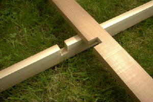
As in my air core loop, the crossarms can be notched, glued and fastened with screws to produce a strong yet lightweight supporting frame for loops up to 10' in diameter.
The loop preamp is powered by 9-12 VDC. Power is fed to the preamp via the coaxial feedline. DC voltage is isolated from the receiver circuitry via a receive coupler.The outer shield of the loop must be opened to create a 'gap' in the shield. This point should be located at the top of the loop, as close to the exact physical center point as possible. The gap does not have to be large, just wide enough to prevent the shielded braid ends from touching each other. Once a small section of shield has been removed, the gap should be thoroughly sealed against moisture. A liberal coating of silicone sealer should be applied and allowed to dry. The siliconed gap should then be wrapped with a layer of plastic cling wrap and then taped.
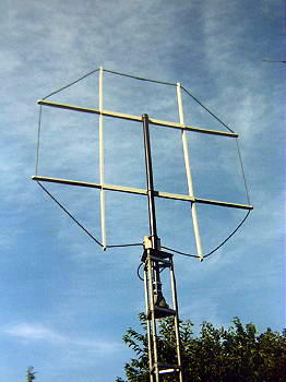
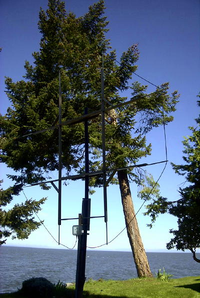
The ends of the loop are terminated in PL-259 connectors to allow the loop to be easily plugged into the preamplifier. The connectors should be 'gunked' and well taped since they are not waterproof. The preamp board is mounted inside a small aluminum die-cast box. Three SO-239 chassis connectors are mounted on the walls of the box to facilitate easy connection of the loop and feedline. The die-cast box is then mounted inside a plastic utility box ( 3" x 6") and the whole assemblage is clamped to the main PVC ( 2") pipe mast. After assembly, the die-cast box lid, the lid of the utility box and all coaxial connectors are liberally coated with silicone sealant. One or two small 'weep holes' should be drilled on the bottom of the utility box to allow trapped moisture or condensation to escape. The preamp box is mounted about 2 inches above the natural ends of the loop so that the last few inches of the loop (along with the male connectors) must be bent upwards and then into the box. This provides a 'drip loop' in the coax ends so that water will not run down along the coax and into the connectors and box (see loop photo).
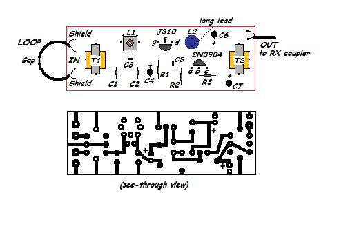
THE PREAMP PREAMP PARTS LIST
T1 - T2 Mouser 42TL004-RC Miniature Audio Transformer ( Xicon ) L1 Mouser 42IF100-RC Miniature I.F. Transformer ( Xicon ) L2 Mouser 43LH268 6.8mH Encapsulated R.F. Choke ( Xicon ) (any value from 4-10mH is OK) R1 75 ohm R2 - R3 2.2K C1 - C2 470pF C3 33-220pf * C5 .05mF C4 - C6 - C7 4.7mf electrolytic * L1 / C3 combine to make a selective BC band trap for your worst (loudest) BC band pest signal. Select C3 to resonate with L1 at the desired trap frequency. Tune the slug on L1 for a null on the trap frequency. C1 and C2 provide a low pass filter with a roll-off of around 400kHz in theory. I have found that in actual practice, roll-off is closer to 500 kHz and more than adequate sensitivity is realized for beacons operating in the 400 - 500 kHz range. Preamp current draw is approximately 14mA at 12 VDC.
* C3 trap values are:
1300-1600 kHz 33pf 1040-1350 kHz 51pf 850-1050 kHz 75pf 700-850 kHz 120pf 550-700 kHz 220pf
THE RECEIVER COUPLER 
The receiver coupler can be built on the same board as the power supply and mounted in a small box or narrow rack panel in the shack.
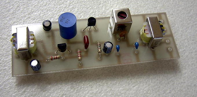
When my original 8' loop (photo) was first built and installed, I noticed a remarkable improvement over my previous 5' tuned air core loop. The five-footer was a very good performer and although mounted inside the house, it had provided regular loggings of many South Pacific and South American beacons on LF. With the new eight-footer, I noticed that many of the Ontario ndb's could be heard every night, even in mid July. As the September DX season approached, many of the Caribbean beacons were nightly regulars along with some new Cuban loggings.I recently rebuilt my loop to 9.5' diameter by adding some short PVC extensions to the wooden arms. Since I had given my previous preamp to VE7BDQ, I also made a new PCB and preamp for the new loop. The PCB design below will fit all of the Mouser components once you have the printout sized properly. If you have trouble, I can e-mail you the original bitmap file which should print out at actual size without any difficulty. Scaling is correct if the distance between the two mounting stud holes for T1 or T2 is 15mm.
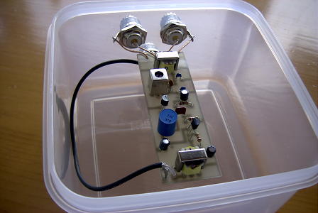
The new preamp was fitted inside a plastic food container for weather protection. Be sure to drill a couple of very small holes on the bottom side to allow any condensation to escape.
Here is the new 9.5' diameter shielded loop using RG8X coaxial cable. Note the PVC extensions added to the original frame. These are pieces of 1" PVC pipe cut in half lengthwise and screwed to the frame.
The shielded loop might more properly be called a 'two-turn' loop or a 'close coupled' loop as this more accurately describes it's behaviour. In actual operation, it is the shield itself that is the active antenna element. Signals picked up by the shield are coupled into the inner conductor, which in turn are coupled back to the receiver via the preamp. The loop is capable of good nulls on both groundwave and skywave signals. The more 'balanced' the loop is (gap placed at exact center), the more balanced the nulls will be.
If you build this loop I would be interested in hearing of your results. Good looping!
![]()