Shown below is my 630m / 2200m experimental station, located on Mayne Island, B.C.
My transmitter (a smaller version of the VE7TIL - designed 2 KW transmitter) consists of two 500W modules, each using a pair of W34NB20 MOSFETS in push-pull. Both modules are driven from the same IC2110 FET driver which is in turn fed from a 4013 binary counter operating in the 'divide-by-two' mode. The oscillator source is an N3ZI DDS feeding a 'divide-by-ten' chip before converting the sinewave to a 5V square wave.
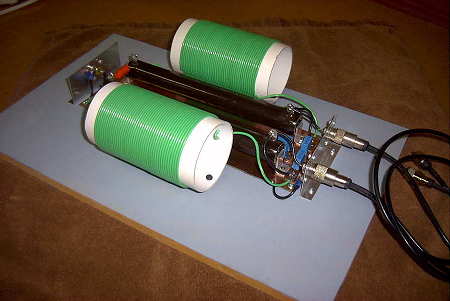
The two 500 watt modules are then fed into a two-port Wilkinson power combiner before feeding the 50 ohm antenna system. The hi-Q power combiners also act as a very effective LPFs.
I have since modified the transmitter for use on 630m. Although the amplifier is not as efficient on this band as it is on 2200m (because of the ferrite core material used in the output transformers), it does generate enough power to get me into the allowable 5W EIRP range. This transmitter is used on both 2200m or 630m simply by plugging in the appropriate power combiner.
For a number of months I have been using a new 630m linear transverter being made and marketed by Roger, VK4YB. Roger sent me one of the early production units for beta-testing and has generously allowed me to keep it, now that the testing phase is over. For my review of this transverter and more information, see my blogspot here.
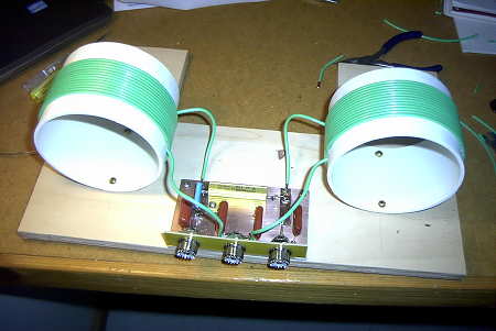
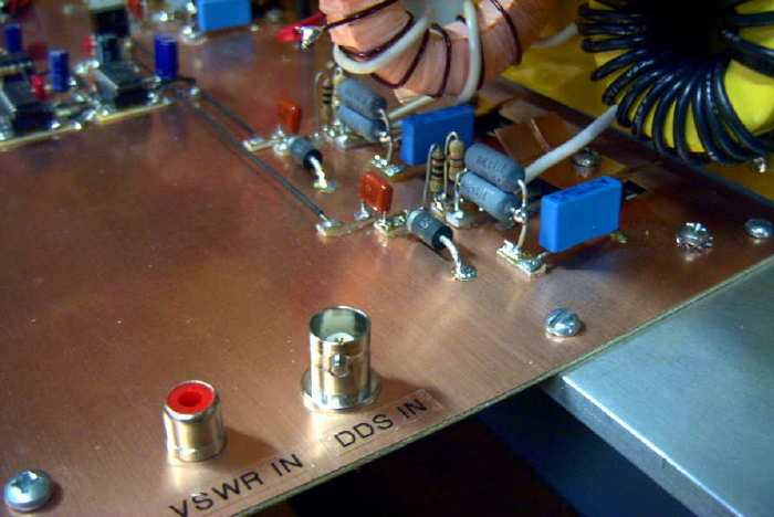
Manhattan construction was used for all stages. The transmitter also utilizes an effective VSWR 'tx-inhibit' circuit to shutdown the FET driver and turn the transmitter off when an abnormal SWR is detected.
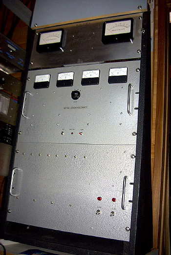
The panel below the transmitter contains four rack-mounted low-voltage power supplies strapped in parallel to run the transmitter, along with a small 12V / 5V supply for the IC's and fans.
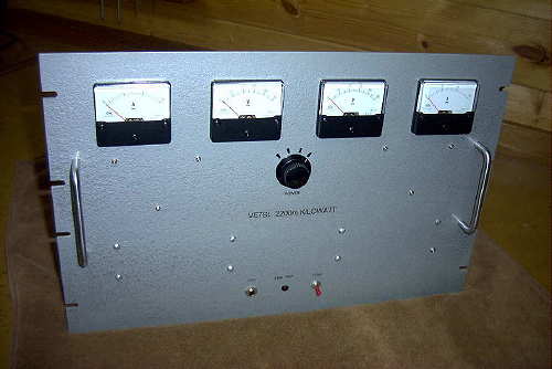
The top panel houses my homebrew 1000W reflected power meter. It is an LF version of the Drake Power Meter, adapted by LX1PD. Circuit details may be found at GØMRF's website. I have been waiting thirty years to use those big surplus Japanese meters in a project. New meter scales were designed using a program called METER.
My station also utilizes a homebrew 'Scope Match' which constantly monitors the transmitting antenna tuning.
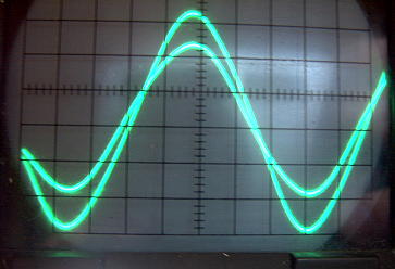
Both antenna CURRENT and antenna VOLTAGE are displayed. This allows easy tuning for resonance as well as making any matching adjustments with the loading coil very easy. The impedance of the antenna can be observed as well as inductive or capacitive characteristics. It is fascinating to watch changes in the scope pattern while the antenna blows in the wind!
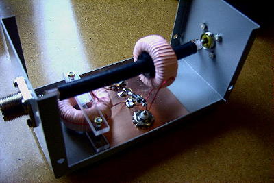
The Scope Match was homebrewed from plans by MØMBU and is shown in both the 'LF Experimenter's Handbook' (G3LDO) and the new 'LF-Today' (G3XDV).
The transmitter is connected and matched to the antenna system by a large antenna loading coil. The loading coil was retired from a local NDB transmitter and is extremely rugged.
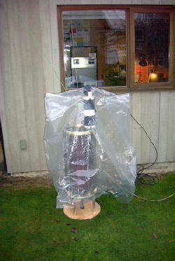
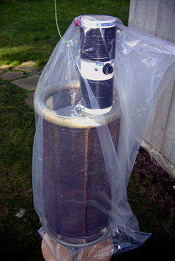
It is air-wound, on ceramic spacers, with #12 copper wire for a total inductance of 2.8mH. My antenna requires less than 2.0mH to resonate at 137kHz so the antenna is tapped down on the coil. A homebrew variometer, between the loading coil and antenna, is used for fine-tuning the system to resonance.
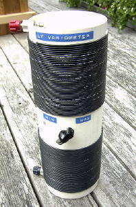
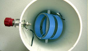
The variometer is a 'variable inductor', with an inner rotating coil connected in series with the outside coil. Rotating the inside coil changes the overall inductance plus/minus 300uH approximately. Plans for the variometer are available at GØMRF's website as well.
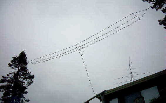
The antenna system is a 'Marconi T' 3-wire flatop. One end is attached near the top of a 100' Balsam tree while the other end attaches to my neighbor's Fir tree. Spacing on the top wires is 1m, with an overall length of approximately 20m. The antenna runs parallel to the ocean beach on the eastern shore of Mayne Island, providing an over-water horizon from KL7 to the north around to W6 in the south. Since taking this photograph, I have modified the antenna by moving the vertical section closer to the high end of the tophat. The overall vertical wire is about 60', the first 20' of which are drooping and almost parallel to the ground. Because of my height above the ocean, at low tide, the effective height of the antenna is ~ 100'.
My ground is very lossy since it is mainly sandstone rock. What power is being radiated is largely the result of the nearby ocean and the saltwater horizon. Tests with locals indicate that this 'ocean gain' is about 6db, consistant with what I have noted on every other band including 2m.