Modifications for the Kenwood
TS-570

19-07-1998 Problem width the
memories
From: PA3HGA@PI8WFL.#NH1.NLD.EU
I bought
last year a Kenwood TS-570D HF transceiver. After a few months of good working i
got a problem : Everytime if i switch off the power i lost all the memories,
including the value for the IF filter bandwidth (menu item 46) which is normally
held even if you reset the transceiver! I thought immediately on a battery
problem. It was, but there was more. I got garanty to this transceiver so i
brought it away for a repair. They tell me it was a known problem by Kenwood
that "a reset IC" was causing this trouble. They replaced a battery and an IC.
Remember this if you got problems with your transceiver !
73, Reg de
PA3HGA
BLOKKER / PA3HGA @ PI8WFL.#NH1.NLD.EU
E-MAIL : PA3HGA @
AMSAT.ORG
19-07-1998 TS570D : durchg.
Sendebere
Hallo , TS570 - Besitzer !
Fuer meinen OV -
Kollegen Peter , DH8PW , habe ich heute dessen TS570D so modifiziert , dass man
damit auch ausserhalb der Afu - Baender senden kann . Da ich diese Mod. hier in
pr nirgends gefunden habe , und weil sie funktioniert , spiele ich sie hier 'mal
ein :
- Alle Kabel abmontieren ( Ant , Stromversorgung , ALC , Paddle usw.
)
- Deckel und Boden abschrauben
- seitlich Schrauben des Bedienteils abschrauben .
- Bedienteil wegklappen , evtl. ganz abtrennen .
- Auf der am Geraet verbliebenen Platine ( X53-3690-10 ) den IC CXD1095Q
suchen.
- Den 1KOhm - SMD - Widerstand ( Aufdruck 102 ) finden und ausloeten . Er
befindet sich links unterhalb des o.g. ICs , rechts neben einer Schraube
.
- Das Geraet wieder zusammenbauen und verkabeln .
- Beim Einschalten auf A=B druecken und damit einen RESET ausloesen . (
Evtl. die alten Voreinstellungen notieren ... )
Fuer die Richtigkeit
uebernehme ich keine Garantie , diese erlischt vermutl. beim Oeffnen des
Geraetes . Ich habe auch keine weiteren Mod. - Tips .
23-01-1999 Kenwood TS-570D MARS/CAP
Modification
This modification is provided "as is".
It is
illegal to operate outside the limits of your class license or permits.
- Disconnect the power cord and antenna coax from the transceiver.
- Remove the top and bottom covers.
- Remove the top screw from each side of the front panel assembly.
- Loosen the bottom screw from each side of the front panel assembly.
- Carefully rotate the front panel forward to gain access to the Control
board (X53-3690-10).
This board is mounted vertically against the body of
the transceiver. It is not the board that is mounted in the front panel
assembly.
- Locate and remove the chip resistor R41 from the Control board.
- Assemble the transceiver then perform the CPU reset procedure by holding
the A=B button depressed as power is turned on.
28-03-1999 TS-570
Batteries
This mods is a copy of the mods from Kenwood TS570
Batteries. Thanks to Al Williams.
It seems incredible, but there is a lithium battery in the Kenwood TS570 that
apparently lasts about 6 months. Replacing it is a major trip into the innards
of your radio.
Clif of AVVID (a
Kenwood Service center) was kind enough to tell me what to do, and I thought I
would write up his instructions and my experience in case someone else needs
it.
According to Clif, the microprocessor must reset correctly or the battery
will drain quickly. Therefore you must follow these instructions, as odd as they
seem.
Before you begin, you need the radio on a nonconductive surface, a phillips
screwdriver and a CR2032 battery (Radio Shack has them). You also need the
radio's power supply hooked up.
- Have the radio hooked up to 12V. Turn the radio off but leave the supply
on.
- Remove the four screws from the top of the case.
- Then remove the 4 screws on the side and lift the top free.
- Turn the radio over and remove the 4 screws from the bottom that holds the
entire case on. Don't bother with the service panel.
- Turn the radio right side up and notice there are 4 screws (2 on each
side) that hold the front panel on. Two of these are in slots, and two are in
holes. Remove all 4 screws. BE CAREFUL. The panel is attached with several
cables and yanking them loose is probably not a good idea.
- Carefully separate the panel from the radio chassis. Note the battery in
the little holder. The + side of the battery is facing out.
- The battery holder is spring-loaded; you don't need to open it. Just
gently push the battery and slide it upwards, freeing it of the holder and
replace it with the new battery (remember + faces you).
- Reseat the panel, lining up the screw holes and replace the screws.
- If you want, at this point, turn the radio on and off again.
- Replace the covers. Remember, don't put the side screws in until the top
and bottom are in place.
That's it! According to Clif the problem won't reoccur. We'll see! Just be
careful when you attempt this. Lots of things can go wrong. The case is very
tight fitting, so don't drop the pieces and bend them out of shape or you will
be sorry. Good luck!
UPDATE
As of March 29th, my battery failed again (yep, about 6 months). I have a
month left on my warantee, so I'm planning on trying to get something resolved.
I'll post here about what I find out.
Kenwood did in fact take the Radio back and apparently installed a diode at
no charge. With any luck, this will fix the problem.
26-06-1999 Kenwood TS-570DG MARS/CAP
Modification
Author: Bill
N0QVW
This is for the DG model only!
- Disconnect the power cord and antenna coax from the transceiver.
- Remove the top and bottom covers.
- Remove the top screw from each side of the front panel assembly.
- Loosen the bottom screw from each side of the front panel
assembly.
- Carefully rotate the front panel forward to gain access to the Control
board (X53-3690-10). This board is mounted vertically against the body of the
transceiver. It is not the board that is mounted in the front panel
assembly.
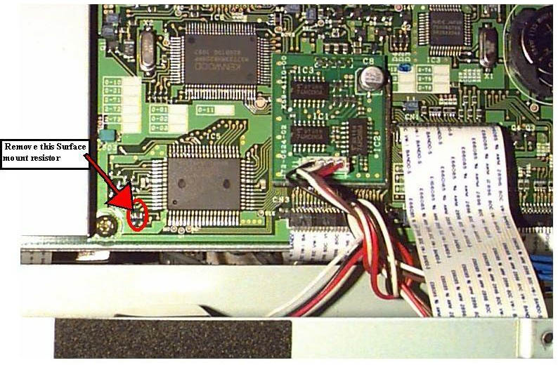
- Remove the square cover with 4 screws on it. LOCATE IC 5 go to the lowest
point by ic 5 there are 2 resistors between the is 5 chip and the screw hole
REMOVE the HORIZONTAL ONE
- Assemble the transceiver then perform the CPU reset procedure by holding
the A=B button depressed as power is turned on.
You will now have all
the other frequencys you couldent transmit on now...
Thanks to Mike Faucheaux [email protected] for
the picture below.
23-04-2000 TS-570 Back-up battery current
drain
Author: Kenwood
Communication, inc.
Service Bulletin no. 1062 (23 January 1998)
When the transceiver is turned off, there is a momentary increase in back-up
battery current drain. In addition, if a personal computer is connected to the
transceiver, excessive back-up battery current drain can occur when the
transceiver is turned off. The following circuit changes will eliminate the
increased current drain.
Caution: This modification requires soldering equipment rated for
CMOS type circuits. It also requires familiarity with surface mount soldering
techniques. If you do not have the proper equipment or knowledge do not attempt
this modification yourself. Seek qualified assistance.
Parts required:
Qty   Description                      New Part No.
 2    10 Kohm resistor                 RK73FB2A103J
 1    Diode                            1SS355         *
 1    470 ohm resistor                 RK73FB2A471J   **
* You can substitute an MA110 diode in place of the 1SS355 diode.
** The
470 ohm resistor is only required for S/N 903xxxxx and higher.
Procedure:
- Disconnect the power cable and remove the covers of the
transceiver.
Access the foil side of control board X53-3690-11.
- Remove the solder resist from three foil locations.
- Cut one foil trace. Do not cut too deep.
- Add the two 10 Kohm resistors and one diode.
- On the component side of the Control board, replace R36 with a 470 ohm
resistor if a 10 Kohm resistor is installed (This must be done from S/N
903xxxxx and higher).
- Remove the lithium battery and measure it's voltage. If it measure 2.8 V
or less, you need to replace the battery with a new one (part number
W09-0873-05).
Battery installation procedure:
Perform the following steps when installing the original or replacement
lithium battery.
- Once the battery is removed from it's socket, wait 20 seconds or more
before going to the next step.
- Connect a power supply to the transceiver. The transceiver should turn on
by itself.
- Install the original or replacement battery.
- Turn off the transceiver from the front panel power switch.
- Reset the transceiver by holding A=B key depressed while turning on the
transceiver from the front panel power switch.
Units with a number 3 stamp on the outside box were already modified at the
factory.
 Time required to make this changes is 1 hour.