Modifications for the Kenwood
TH-75

19-07-1998 TX across entire tuning range
TH-75A
I have a couple of mods that you may or may not have. For
the TH-75A MARS/CAP mod, removing D4 will allow TX across entire tuning range,
except that actual TX range will be limited by tuning of the PLL.
For the
TM-731A, there is a "Beyond MARS/CAP transmit Modification". It provides TX from
136 to 174 and 400 to 500 MHz. Again, actual TX range limited by PLL tuning. If
you don't already have this and would like it, I'll send a copy if you furnish
me your address. It involves cutting R25 on the control unit, and installing a
jumper (diagram required to locate position), then two resets in a row.
I
have tested these mods on my own rigs.
73 - Kevin, KD2SL @
KC3BQ
19-07-1998 9600 baud
with the TH 75
I tested the follwing modification only for the
430 MHz part. Perhaps it works also on 2 meters if you try the modification on
the 144 MHz IF-Unit.
For opening the TH 75 follow the instructions of the
manual page 31 ( installation of the TSU-Unit ).
After opening the handy, it
is not necessary to disconnect any connectors between the front and rear part.
All connections have to done at the rear part.
-TX-
On the right
side of the open handy is a connector (No. 201). The wires of this connector are
leading to the lower board of the rear Part.
Disconnect this connector. Next
remove the five screws holding the upper board. Now it is possible to lift this
board for about 5 mm.
On the lower side of the board are the solder pins of
the connector which was opened before. Solder a thin wire to pin No 5. (Start
counting at the antenna side of the TH 75).
This wire can be connected direct
to the TX-Exit of your TNC, if this exit has A/C level only. If the TNC has also
D/C level add a capacitor of about 4.5 to 6.8 uF.
-RX-
A little
bit higher to the connector were the TX line was connected is the UHF - IF unit
(X58-3610-00). It is a small additional board over the main board. You will find
the IC TK10485M on this small board. Solder a wire to pin No 11, the first one
the left side (Start counting again at the antenna Side). This pin is connected
to a capacitor. In order to prevent the IC from being demaged, I recomment to do
the soldering at this capacitor.
This wire can be connected direct to the
TNC.
If you need for some reason the squelch of the TH 75 during 9K6
operation, add a resistor of 10 KOhms in the RX line.
These are all
modifications necessary for 9K6, and now you can start closing the TH 75. If you
do not instaubber cap of the DC IN Terminal, you have a fine little gap for the
wires. But it is also possible to install an additional jack if the TSU-6 unit
is not installed. The ground connection can be made via the speaker jack. The
PTT line of the TNC should be connected to the MIC jack.
The TH 75 is able to
work with a TX-Delay of 150 - 170 ms (> T15) which is a good value for a
modified PLL TRX.
19-07-1998 TH-75A MARS/CAP
modification
This modification will allow the TH-75A to transmit
from 142 to 152 MHz and 420 to 450 MHz. Specifications are guaranteed for the
Amateur Bands only. Through the transceiver will display 136 to 174 MHz and 335
to 512 MHz, the PLL circuit may not lock through the entire
range.
Modification procedure
- Disconnect the battery and antenna.
- Remove the three case screws and two battery plate screws.
- Lift the front panel from the body of the transceiver, but do not
disconnect the two flex cables.
- Cut the green jumper wire (W1) that is located to the left side of the CPU
in the front panel assembly.
- Assemble the transceiver by reversing steps 1-3.
- Reset the CPU by holding the M key as the power is turned on.
I
have tried it and it works.
Suresh Kagoo N9GSA
Internet :
[email protected]
Bitnet : SKAGOO@MEMSTVX1
31-03-1999 TH-75E auf
9k6
de DL8FCL @ DK0MTV.#RPL.DEU.EU
Seit einigen
Tagen benutze ich ein TH-75E mit recht gutem Erfolg für PR mit 9600 Baud. Der
Umbau ist sehr einfach durchzuführen, und sollte jedem gelingen, der schon
einmal einen Lötkolben in der Hand hatte.
Zuerst öffnet man das Gehäuse.
Die zu entfernenten Schrauben kann man sich auf der letzten Seite der
Bedienungsanleitung anschauen (Einbauanleitung für CTCSS unit TSU-6). Das Gerät
soll selbstverständlich spannungsfrei sein.
Alle Anschlüsse werden an dem
rückwärtigen Teil des Handies angelötet, aber man muß die Verbindungen zu dem
vorderen Teil (der mit der Anzeige und Tastatur) nicht
abtrennen.
--TX--
Auf der rechten Seite sieht man eine
Steckverbindung (Nr. 201), deren Kabel nach unten in das Gehäuse verschwindet.
Diese Verbindung muß man vorsichtig lösen. Nun löst man die 5 Schrauben, mit
denen die gesamte Platine mit dem Rest verbunden ist. Jetzt kann man die Platine
etwas nach oben biegen und sieht an der Unterseite die Lötstifte der
Steckverbindung, die man zuerst gelöst hat.
An den Stift Nr. 5 von oben
gezählt lötet man einen dünnen Draht. Diesen Draht kann man direkt mit dem
TX-Ausgang des TNC verbinden.
--RX--
Ein Stück oberhalb der
Steckverbindung, an der das TX-Signal eingespeist wird befindet sich die UHF IF
Unit (X58-3610-00) als eine separate Platine, die auf die Hauptplatine
aufgesetzt ist. Hier muß man den RX-Anschluß anlöten, da dies direkt an dem
Diskriminator geschehen muß. Der richtige Punkt ist der Pin Nr.11 des IF-IC
TK10485M. Dies ist der auf der linken Seite der 1. von oben gezählt. Von diesem
Pin geht die Leiterbahn zu einem Kondensator. Ich habe den Draht an dessen
Kontakt in Richtung IC angelötet, damit ich auf gar keinen Fall das IC
beschädige.
Das war es, man kann das Gerät wieder zusammenbauen. Die
Drähte kann man neben der Stromversorgungsbuchse nach außen führen, wenn man die
Gummikappe wegläßt. Dort gibt es dann einen kleinen Spalt der sich dafür eignet.
Man kann aber auch eine kleine Buchse in das Gerät direkt über dem Lautsprecher
einbauen. Dies geht allerdings nur, wenn die CTCSS-Unit nicht eingebaut wurde.
Die PTT-Leitung des TNC schließt man ganz einfach an die Mikrofonbuchse mit
einem 3,5 mm Stereo-Stecker an. Dadurch ist auch das eingebaute Mikrofon
abgeschaltet. Die Masseverbindung stellt man am Besten über die
Lautsprecherbuchse her. Das hat den Vorteil, daß auch der Lautsprecher
abgeschaltet ist. Er neigt sonst zu Knackgeräuschen, selbst wenn die NF ganz
zugedreht ist.
Ich habe noch keine Messungen (Augen-Diagnostik, BERT)
durchführen können, aber praktische Tests auf DB0SPC haben zu vorzüglichen
Resultaten geführt. Das TX-Delay habe ich auf 150 ms eingestellt, und bin in der
Lage 5000 Bytes in weniger als 15 Sekunden auszulesen. Ich verwende einen TNC2H
der Fa. SYMEK und habe bei der Einstellung des Sendefilters die besten
Erfahrungen mit der Einstellung Nr. 1 gemacht. Die Einstellung des Hubes im TNC
war auch nicht sehr schwierig, ich habe ganz einfach mit dem geringsten Hub
angefangen und dann langsam aufgedreht, bis der Digi mir antwortete. Danach habe
ich etwas oberhalb dieses Punktes hin und her gedreht, bis ich die besten
Resultate erziehlte.
Für eventuelle Fehler übernehme ich natürlich keine
Haftung, bin ich aber gerne bereit Fragen zu beantworten.
Ich wünsche viel
Spaß beim Basteln und bei PR mit 9K6.
vy 73 es 55, Walter DL8FCL @
DK0MTV
20-04-2000 TH-75A No
TX on VHF using a vehicle battery supply
Author: Trio-Kenwood Communication,
inc.
Service Bulletin no. 957 (9-1-1990)
When the TH-75A is connected to a vehicle battery, ignition or alternator
noise can be induced on the DC line. When the transceiver is in the automatic
battery saver mode, the noise pulses overcharge C348 on the RF board causing it
to short. The supply current opens L218 and the foil trace at this coil. To
protect the transceiver, a Zener diode will be used to clamp the SBR line.
The Zener should be solder between the SBR side of L218 and the shielding
case of L221 on the component side of the RF board (X53-3370-11) (A/3). The
Service Manual disassembly instructions will be required to perform this
modification.
Note: This modification has already been performed on models stating
with serial number 007xxxx.
Required part:
22V Zener diode (UZP-22B)
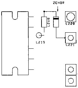
This is an optional change that is not covered under warranty.
Time to
perform this modification is 1 hour or less.
21-04-2000 TH-75A Intermittent memory
loss
Author: Kenwood
Communication, inc.
Service Bulletin no. 978 (8-8-1990)
Some TH-75A owners have reported that the transceiver intermittently loses
its memory channel information after transmitting. Other users have reported
symptoms such as key board lock up after transmitting. The following
modification will re-configure the PTT input to the microprocessor to correct
these conditions.
Required parts:
33 Kohm chip resistor      RK73GB1J333J
470 pF ceramic capacitor   CK45B1H471K
PTT tactile switch         S40-1415-05
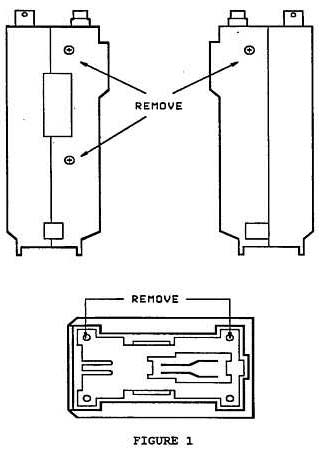
- Disconnect the battery and antenna.
- Remove the three case screws and two battery plate screws. Figure
1.
- Lift the front panel from the body of the transceiver and disconnect the
two flex cables. To open the connectors push the tabs towards the flex cables
and gently lift up. Figure 2.
- Remove the 4 screws from the Control board inside the front panel. Figure
3.
- Remove the 3 screws from the speaker mount. Figure 3.
- Carefully lift the Control board, PTT switch assembly, speaker, and mic
element from the front panel. Do not break any wires.
- Lay the Control board on a soft cloth to avoid scratching the LCD.
- Locate chip capacitor C2 on the Control board. Figure 4.
- Replace C2 with a 33 Kohm chip resistor.
- Remove the protective coating from the foil between pin 58 of the
microprocessor and chip resistor R8. Presolder the exposed foil. Figure
5.
- Size, cut, and bend the leads of the 470 pF ceramic capacitor and then
install the component between pin 59 of the microprocessor and the ground side
of the 33 Kohm chip resistor. Figure 6.
- Remove the screw from the PTT switch assembly and then remove the rubber
PTT cover from the board. Be careful not to lose the black plastic plate that
fits inside the rubber cover.
- Remove the PTT switch from the board.
- Cut the tabs off the bottom of the new PTT switch to allow the switch to
lay flush on the board. Figure 7.
- Install the PTT switch.
- Assemble the transceiver.


Time required to perform this modification is 1 hour or less.