Modifications for the Kenwood PS-430


19-07-1998 No protection on Powersupply

Hallo Guys.
I had have some problems with originale Kenwood Powersupply (PS-430) The final-solid-states has brooken on it, so absolutly no protections on this Equipment, and the full 24V DC came to my rig. And i seen it only when the ventilator beginns to run, (faster as usual) so some minutes i had 24V on my TS-690S , because the display on this Rig has no usual scale-lamps.
But it seem to be, no dommage on the Rig detectable for the moment.
When i repaired than the supply i made a little change on it. So take a look on your Powersupply iff they has an overvoltageprotection, iff not you can use following very simple, but sure circuit.

                                                          +13.8 V <- from 
                                        _________________________ Regulation
   -> +24 V     Fuse                    ¦
       ________¦----¦_________          ¦
               ¦----¦        ¦         /   Zd 14 or 15V 1W
                             ¦        /---
                             ¦          ¦
                             ¦         _¦_
                         Th  ¦         ¦ ¦  R1 100 1/2w
                           __¦__       ¦_¦
                              /        ¦
                             /         ¦
                             ¦\_________¦
                             ¦          ¦
                             ¦         _¦_
                             ¦         ¦ ¦  R2 1K 1/2w
                             ¦         ¦_¦
   -> -24 V                  ¦          ¦
      _______________________¦__________¦______________________
Explication :
Iff the Outputvoltage (13.8V) came over the Zenerdiode + the ignition-voltage from the Thyristor, this will be Shortcircuit the +24V and the - So the fuse will be smelting, and no dommage on your Equipment.
Important the fuse and the Thyristor must been adapt to your Power, not that the Thyristor are broking and the fuse not.


16-04-2000 PS-430 Voltage increase with TH-205/215
Author: Trio-Kenwood Communication, inc.


Service Bulletin no. 938 (2-6-1988)

When the PS-430 is used as an external D.C. power supply for the TH-203/215, the output voltage may increase to approximately 20V due to RF feedback. This condition is restricted to operating in the high power mode with the supplied helical antenna. Adding a by-pass capacitor between the base and emitter of Q2 on the AVR board of the PS-430 will correct this occurrence.

Required parts:
1000 pF, 50V capacitor (CK45B1H102K)

  1. Remove power from the PS-430.

  2. Remove top cover of the power supply (10 screws).

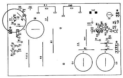
  3. Locate transistor Q2 on the upper left hand side of the AVR board (X43-1440-00). The transistor and thermistor TH1 are covered with a piece of shrink tubing to keep them in close contact with one another.

  4. Remove the shrink tubing from Q2 and TH1.

  5. Tack solder a 1000 pF capacitor between the two outside leads of Q2 (base and emitter).

  6. Reinstall the shrink tubing (if it no longer fits, just make sure that the thermistor is in physical contact with the transistor).

  7. Reinstall the top cover.

This modification is not covered under warranty.
Time required for this modification is ½ hour or less.