** R-5 is closed when shunt feeding the tower on 160m. The relay by-passes the choke balun and grounds the elements to the tower. |
RELAY LOGIC
|
|
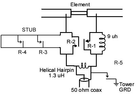
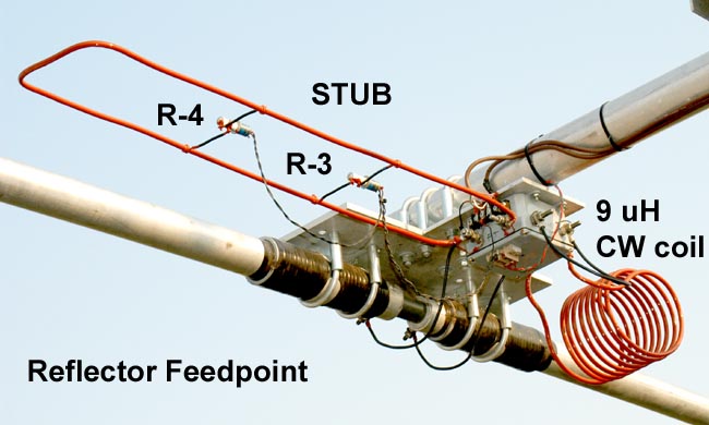
ELECTRICAL: BAND SWITCHING (80m) This short boom, loaded yagi has a very narrow 25 kHz optimized bandwidth. (As described later in the tuning section, the bandwidth of the Yagi is VERY sensitive to reflector tuning) It was decided to include 4 relays to switch various series inductors at the feedpoint and reflector element to shift the operating window. One inductor (stub with 2 relays) will shift the resonance down 10, 20 & 30 kHz and the other down 270 kHz into the CW band. With this arrangement using various combinations of coil/stub selection, the bandwidth is expanded to 60 kHz in both the CW and SSB parts of the band. For DX work, this is adequate because of the narrow DX window: SSB 3815-3760, CW 3550-3500 (during DX contests this may not be sufficient coverage). See below for the the relay switching logic. Two identical switch boxes where constructed. One installed at the driver and one at the reflector element (no hairpin coil). The series inductors are a 4" diameter air core, 1/4 " copper tubing coil and a 1/4" copper tubing stub. |
|
** R-5 is closed when shunt feeding the tower on 160m. The relay by-passes the choke balun and grounds the elements to the tower. |
RELAY LOGIC
|
 |
SWITCH BOX Vacuum relays R-1, R-2 and R-5. Relays R-3 and R-4 are mounted externally onto the stub. See Below Vacuum relays: (Jennings RF5A-26S) 12 amp. 7.5 kv. Available here: MAX-GAIN systems for great used pricing.
|
 |
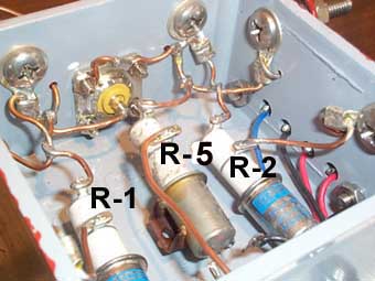
A view of one of the switch boxes mounted at the reflector. Stainless steel hardware provides electrical and mechanical support for the inductors, but redundant solder connections using copper wire are also included.
|
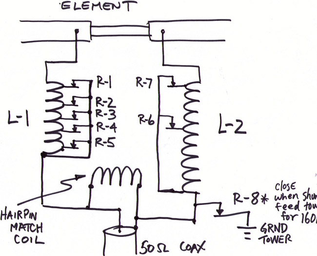
NEW (Expanded) BAND SWITCHING (2007)
 |
|||||||||||||||||||||||||||||||||||||||||||||||||||||||||||||||||||||||||||||||||||||||||||||||||||||||||||||||||||||||||||||||||||||||||||||||||||||||||||||||||||||||||||||||||||||
|
At left is the relay logic. All Vac. relays are normally closed. Relays noted on the chart are energized and OPEN. |
 |
The switching relays and coils are mounted in a 12"X14"X6"
weather-proof plastic box. At the top is the reflector switch box (NO hairpin match coil)
At the bottom is the driver switch box |
 |
A close-up view of the driver switch box. The coils are made of 1/4" copper tubing and are 4" in diameter. All relays are Jennings RF5A-26S vacuum units: 7.5kV and 12 Amps. Great deals for these relays at MAX-GAIN systems |
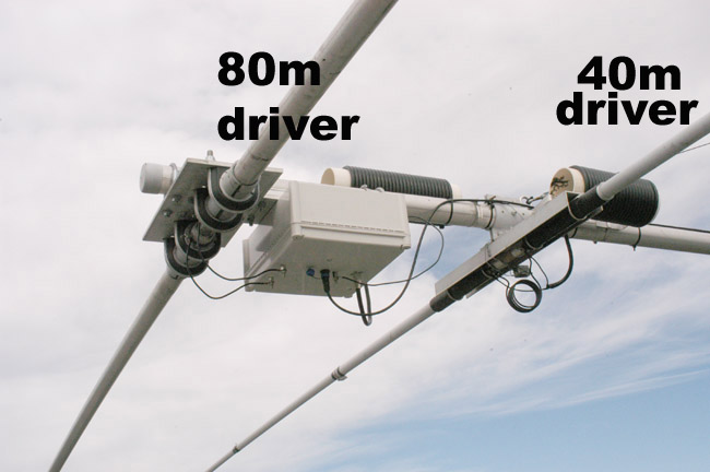 |
At left is a photo of the new enclosed switch box mounted
at the driver.
|