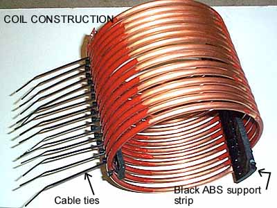
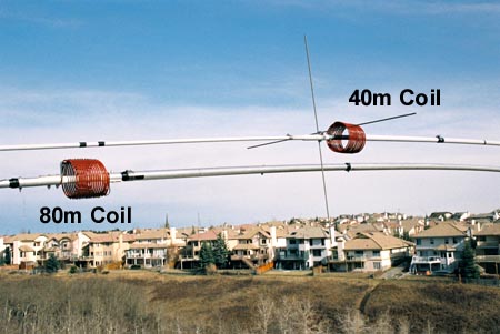
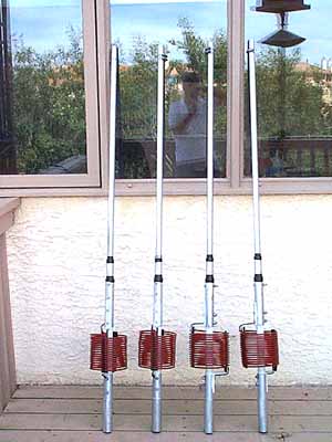
1 1/4" solid fiberglass rod is used for the element split insulator.  The split is 8 " long. The coil is 15.5 turns of 1/4" copper tubing, 6.2" dia. and 6" long.

Mouse over the photo at right to see the end view.

COIL DESIGN-ELECTRICAL

Using a DOS program from Brian Beezley K6STI, it was possible to design some low loss loading coils. Working with the program it became clear that not only conductor size and coil dimensions were important, but form loss plays a significant role in determining Q. The final loading coil design was 15.5 turns, 6.2" diameter, 6" long using ¼" copper tubing. Using an AIR core this coil shows a Q of over 1300 with a loss of only .5 ohms (3.8 MHz). This same coil design using a PVC form has a Q of only 250 with 3.5 ohms   of loss. (See screen shots below) The program provides a choice of 15 different form materials. The final physical coil design at VE6WZ is "mostly air core" and will probably show and sustain a Q of around 500 to 1000 (loss .7 to 1.5 ohms). This is likely better, or at least comparable to the small gauge linear loading wire approach. (See here for some good info. on loading coil design by Tom W8JI )

End view of loading coil
Air Core:

Q=1339

Loss=.5 ohms

PVC core:

Q=254

Loss=3.3 ohms

COIL DESIGN-MECHANICAL

Two black ABS strips cut from 4 " pipe where used to support the  ¼"copper tubing coils which where attached with black UV proof nylon cable ties.  The ABS strips provide adequate mechanical stability to support the entire coil weight with two opposing aluminum brackets. Electrical redundancy was implemented by using 10 ga. copper wire soldered to the tubing and mechanically clamped to the element.  To minimize parallel losses due to weathering the copper tubing was painted with red electrical insulating varnish.


Electrical insulating enamel paint
A view of both the 80m and 40m high Q coils.

The 40m coils are 11.5 turns of 3/16" Aluminium tubing, air wound 5" diameter and 5" long.  They worked as almost exact replacements for the original Cushcraft XM-240 coils.  See here for details.

A frosty morning at VE6WZ At left: One of the problems with this Yagi design in a cold northern climate.....what is the inductance of this coil now??

During very wet weather and frosty conditions like this, the Yagi tuning can be greatly effected.


NEXT......Band switching