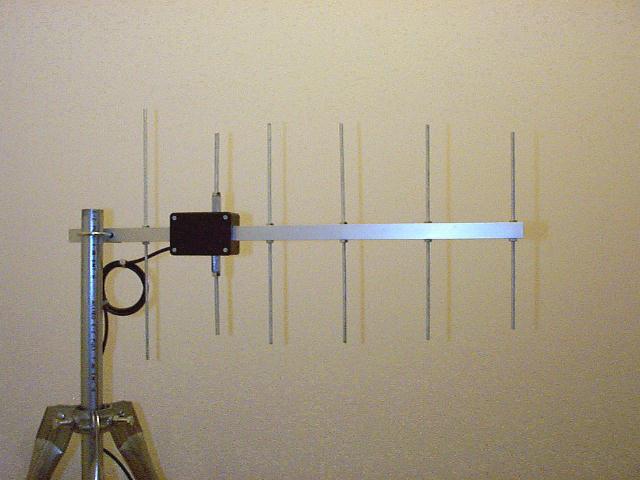
6 element UHF Yagi antenna
This is a standard 6 elements design scaled for UHF application. All material used in this project are easily obtainable tubes and rods which is limited within a total budget of $18.
Design background
Element dimension in inch unless otherwise specified.
|
Element |
Reflector |
Drv. Element |
1st director |
2nd director |
3rd director |
4th director |
|
Diameter |
0.18 |
0.25 |
0.18 |
0.18 |
0.18 |
0.18 |
|
Length |
7" |
6.3" |
5.8" |
5.6" |
5.3" |
5" |
|
Spacing from Drv. element |
- 3.8" |
0" |
2.9" |
6.8" |
11" |
15" |
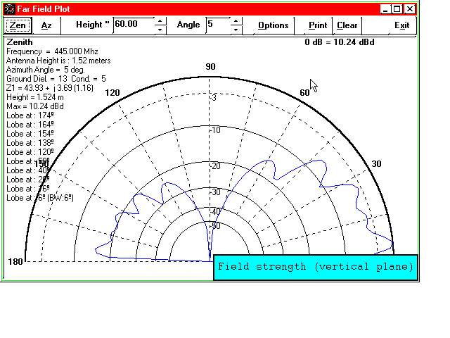
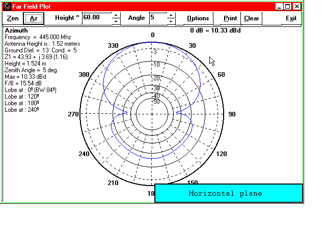
Based on computer simulation, this beam should have a forward gain of 10dbd while F/B ratio will be close to 16db. Usable bandwidth (SWR < 1:1.5) well exceeds 10MHz. Performance of the real product closely resembles the expected characteristic. The beam has been duplicated several times while a consistent performance in SWR, and directivity was obtained.
Constructing process
One of my concerns is how to maintain accuracy in dimension of the elements during drilling activities (via hand held tools instead of drill press), A 7/8" square tube is thus chosen as the boom material. Their flat surface makes it much easier to be drilled. All reflector and directors are made of threaded rods (10-24 diameter) while driven elements have a slightly larger diameter of 1/4". This difference has nothing to do with radiation efficiency (although the larger dimension does cause a difference in resonance length). 1/4" diameter is chosen just because that is the smallest size where matching nuts with long body are available. The nut is required so that length adjustment of the driven element is possible.
The element length dimension (not spacing) listed in the above table refers to brass material. If elements of other metal are employed, the length will change. Threaded rods on the market are usually made of three types of metal - brass, plated steel and stainless steel. To make it simple for cutting estimation, steel based metal needs shorter element length. The reduction factor is about 75-80% of brass. The length for reflector and directors are not too critical since they will compensate with each other. The length of the driven element is the most critical since it will have direct and severe impact of the SWR response of the antenna. Easy adjustment of driven element length is thus essential for the success of the whole project.
A 2"x3"x1" plastic box is used for the mounting of two driven elements. Two square holes are opened on the box allowing the boom to penetrate. Driven element position can be adjusted by sliding the box on the boom. This will be handy when trimming of the antenna's high / low frequency response limit is required.
The driven element is a combined mixture between 1/4" threaded rods, nuts and bolts. The DE pair is mounted on a plastic box that provides insulation and water proofing protection. The RG-58U feed line is first routed inside the square tube. The spliced ends (core and screening layer are then leaded through two holes on the tube and be connected directly with bolts and nuts of the driven element. There is no need to install balun for matching (although having one installed will help maintain a more balanced radiation pattern). .
All threaded rods have to be prepared as listed in the above listed dimension. Vertical holes are then drilled on the square aluminum tube while the finished elements are mounted on the tube through these holes with lock nuts.
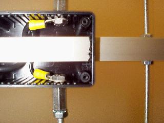
Core conductor and shield of the RG-58 connected to both driven elements.
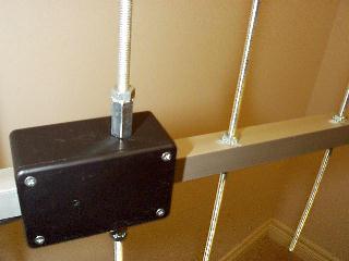
The adjustable section of the driven element -
Tune up procedure
In order to tune the antenna, it must be prepared and be mounted on an environment that will be close to the final expected operating condition. I use a tripod with a 4-ft pole as a temporary test jig. This provides a ground clearance of about 5-ft. for the yagi. The antenna is first connected to a transmitter via an in-line SWR meter. The transmitter should be able to work on at least three frequencies - the low, center and high limit of the expected operating band. With the antenna placed in an area with at least 5-10 ft clearance from nearly objects, key up the transmitter on all three spots and mark down the observed SWR. Trim the length of both elements for the driven element in equal status unless a dip is observed and lies on the center of the expected operating range.
To test the directivity of the antenna briefly, one can use it to monitor signal from a far away station. By making azimuth changes 360 degree around, the changes in the received signal can tell the general 3db-beam width characteristic.
Feel free to Email me if more detail is required.
Patrick Wong Oct-98.