Low-Resistance Meter
This project is a simple
low-resistance meter. I used to call it a milliohmmeter but in fact it
is good for measuring at best hundredths of ohms, and I'm not sure what
you call that. I've seen it called a "low ohms meter" elsewhere. It's not as accurate as
a commercial unit but should be adequate for hobby use. I used an
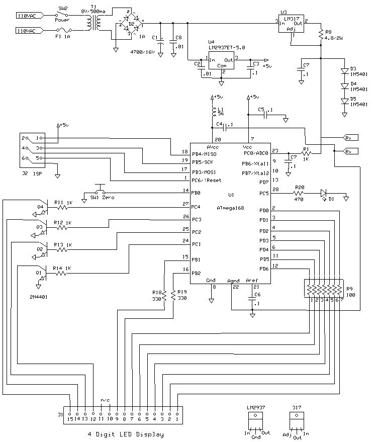
AVR ATMega168, mainly
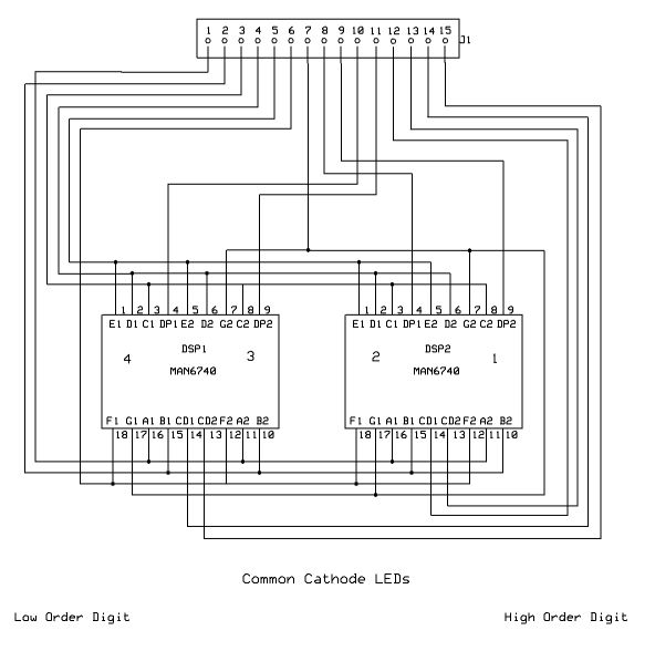
because of its built-in 1.1 volt A/D reference. The LEDs are ancient
MAN6740s from my junkbox; try to use something more modern that is
brighter. Then you should be able to increase R9 from 100 to perhaps
470 ohms or more.

A LM317 is used as a 250 mA constant current source (U3). This
is passed through Rx, the unknown resistance, and the voltage dropped
across Rx is sampled by the AVR's A/D converter, using the internal 1.1
volt reference. Diodes D3, D4 and D5 are used to clamp the A/D input to
around 2 volts, to prevent the AVR from seeing overvoltage when no
resistor is connected.
The AVR program samples the input and calculates the resistance of Rx. The result is displayed as a 4 digit number.

There are a number of issues regarding accuracy. The
problem is that very small resistors produce very small voltage drops
across them, unless the current is high. At first I wanted to use
a 1 amp current source, but heat in the power supply was a problem, and
I ended up using 250 mA. This is a compromise which limits the lower
end of the resistance scale that can be measured. Because of the small
voltages presented to the A/D, resolution is a problem, and although
the readout resolves to the millivolt, the lowest order digit is not
reliable. To illustrate the problem, a count of 1 difference
from the A/D may calculate to 5 or more milliOhms, so you can't use this as a milliohmmeter.
Other
problems
are the resistance of the wiring and binding posts used in
construction, and noise in the circuits. The former problem is
addressed with the "zero" button. Place a very heavy short across the
Rx terminals. A reading of around 30 mOhms may be displayed. Press the
zero button and the display should become 0. Then the unit is ready for
measurments. The correction factor is saved in eeprom, so should not
require repitition too often. I deal with noise (which apppears as
jitter on the display) by the use of a digital filter, which provides
the median of the last 15 A/D samples. Consider that we're
trying to divide the
1.1 volt reference into 1024 steps, which is close to 1 mV per step.
The
code has two defines that should be updated for your hardware.
CURRENT_MA can be measured by placing your digital ammeter across the
unknown resistance terminals (Rx). It should read close to 250 mA.
The current is a function of resistor R8. Next there is VREF_MV.
The 1.1 volt internal reference of the microprocessor is used, and can
be measured by an accurate digital voltmeter at pin 21 (Aref) of the
ATmega168.
Download C
source code for the meter
Back
to VE3LNY's AVR Project Page