Equivalent Series Resistance Meter

Equivalent Series Resistance (ESR) is a problem with some types of capacitors. When its too high, the capacitor may measure correct capacitance, but be useless in the circuit. I came across this project to build an ESR meter. It is simple and I wanted to build one right away. What stopped me was the meter, which required a custom, non-linear scale. I know its possible to make custom scales for meters, but it is something I really don't care to do. Then I thought, OK why not use a microcontroller and digital readout? Measure the voltage with an A/D port, convert the value to ohms and output on the LED display. I chose an ATtiny861, which has A/D and plenty of I/O for the job.

schematic page 1esr meter schematic page 2

Actually the meter wasn't the only problem with this project. I also had difficulty with the transformer, T2 in my schematic. 
Mornhinweg says:

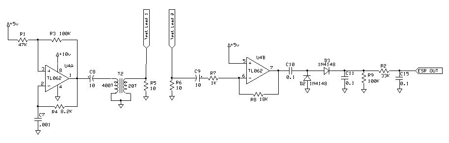
"The only part that could pose problems to inexperienced builders is the transformer. I made mine using an Amidon ferrite core, type EA-77-188, which is a tiny double-E core having a cross section of  22mm2, and external dimensions of  about 19x16x5mm total. I used the nylon bobbin that Amidon delivers with it, wound a primary winding consisting of 400 turns of AWG #36 wire, and as secondary I wound 20 turns of AWG #26 wire. If you have a larger or smaller core, you can adjust the turn numbers in inverse proportion to the cross section area. The wire size isn't critical - the gauges I used are about 3 or 4 numbers thicker than necessary, while at the same time this bobbin has room for wire at least two numbers thicker than the ones I used. Thus, you can choose from about 6 different wire gauges for each winding, with negligible impact on the performance."

I didn't feel like ordering the core he used, so I turned to my partsbin instead. Lots of unknown toroid cores which may or may not work. Then I spotted a ferrite cup-core with a bobbin inside, rescued from a PCB long ago. The bobbin had two separate windings that looked the same size and used the same thin guage wire. I unwound one side and counted the turns: 100. Since he called for 400 turns to 20 turns, I figured that 100 turns to 10 turns might work OK. So I wound 10 turns on the empty side and put the core back together. As it turned out, the hacked transformer worked just fine!

There is a small difference in my schematic. R8 is 18K, compared to 39K in the original. This was to bring the maximum rectified output of U4B from around 6V down below 5V for the AVR's A/D input. This will be very dependent on T2 and you may have to fiddle with the value yourself. You can get the maximum output by shorting the capacitor test leads together.

front viewInside view


I mounted the display, switch and pushbutton on a small circuit board and cut holes in the case and mounted the board to the front of the case, using the switch and button to hold it in place. The test leads are soldered directly from the circuit board to the binding posts, to avoid connectors whose resistance can cause problems.

How well this unit works depends on how well you calibrate it. Since your analog section will produce a different signal level than mine, you have to edit interpolate.c and recode the tables there with your own data.  
Mornhinweg doesn't talk about it much in his article but I'm sure that every builder of his circuit had to painstakingly calibrate the meter as well. With an accurate voltmeter, measure the voltage at pin 20 of the microprocessor (or the junction of R2 and C15). Short the test leads, which gives you the maximum voltage output from the analog section. It should be between 4 and 5 volts (to give the A/D the greatest range to work with). If necessary, adjust R8 to bring it into range. You don't want to exceed 5 volts. which is the limit of the A/D. OK now you know the max voltage corresponding to 0 ohms resistance, edit common.h and look for "#define SHORT_MV" and change the value there to your value in millivolts.

Next you have to use a bunch of resistors between 0 and 100 ohms and measure both resistance and voltage, and place them in the tables in interpolate.c. I used a 100 ohm potentiometer, stepping it through its range and plotting 34 values. My table contains a total of 35 entries. You could have more or less entries (make sure you update "#define NR_ENTS"), but more entries means better accuracy. I plotted my table on a sheet of log graph paper and the curve is very non-linear, which means that linear interpolation between two widely spaced entries will give inaccurate results. However, in this application high accuracy is not necessary.

The "zero" button is intended to force the meter to show 0 ohms when the test leads are shorted. It remembers the last value in eeprom so unless something changes, you should not need to use it often. Keep in mind that it overrides the 1st entry in the MV->ohms table in interpolate.c, but the remaining entries are not affected. If the unit's calibration changes for some reason, you should go back and recalibrate it for best results.

After testing a bunch of capacitors from my parts bin, most showed 0 or 0.1 ohms, but one older one showed over 10 ohms, and was consigned to the wastebin.

Download C source code for the esr meter

Back to VE3LNY's AVR Project Page