Appliance Timer
Yes I know you can buy an appliance timer at the
store for 10 bucks or so but as usual I have my problems with those.
For one thing, they use batteries inside that run down at inconvenient
times. For another the user interface is arcane and I have trouble
programming them. The clocks are not accurate, and must be reset often. Finally they are so cheap the buttons and switches don't
work properly and fail after a while.
I use a timer to turn a lamp
on at night and off in the morning. This is simple enough, but where I
live, daylight hours vary substantially throughout the year. The timer
must be reprogrammed every couple of weeks. Now if I designed my own timer,
I could create a program with a table of on/off times for each week of
the year. You can't buy that feature at the store.

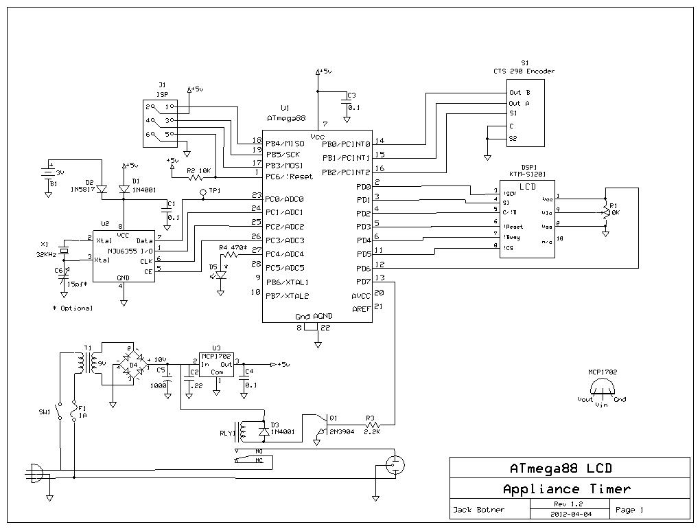
I had acquired a few KTM-S1201 LCD displays, which are 12
numeric 7-segment digits. I wanted to use one in this project, but some
alphabetic prompts were necessary. I wrote a module to do this, using
the best fit upper/lower case letters for the 7 segments. The result is
not pretty, but works.
The only control is
a rotary encoder/pushbutton. Once set up, the unit displays the time in
24 hour format. Turning the knob either way turns the attached appliance on and
off. Pushing the button puts you in setup mode, where a menu is
displayed and managed by twisting the knob and pushing the button. You
can set the on time, off time, set the clock, and so on.
The
battery is a 3 volt lithium cell which I had on hand. It runs the clock
when the unit is unplugged. You can use one of those small 3 volt coin
cell batteries if you prefer. The 5 volt regulator I used is a
MCP1702-5002E/TO (Digikey P/N MCP1702-5002E/TO-ND) however a 7805
should work just as well.

The rotary encoder is a CTS series 290 rotary encoder. More information on this part can be found on my rotary encoder page.
I
found relay RL1 in my parts bin. The coil is 12VDC, but works fine with
my 10 Volt supply, switched through Q1. The contacts must be able to
handle the load's current and voltage (a small fluorescent lamp in my case).
There are two operating modes, Run and Setup. When powered up the display shows the time
in HH MM DD (24 hour) format and the unit is in Run mode. If you twist the knob,
the appliance switches on and off, as a manual override. If you push
the button, the program goes into Setup mode and displays the
1st menu item. Twisting the knob moves up and down on the menu.
Pressing the button selects the menu item for further processing. The
menu items are:
� Run - pressing the button returns you to run mode.
� Timer
On/Off - This option turns the timer function on or off. The menu item
shows what the changed state will be, so when the timer is on, it will
say Timer Off.
� Set Clock - You must do
this once to set the RTC. With each push of the button you can set
year. month, day, hour and minute. After the final button push the time is set
with zero seconds.
� Set On Time - to set the timer ON time, hours and minutes.
� Set Off Time - to set the timer OFF time, hours and minutes.
� Prepgm
On/Off -works similar to Timer On/Off. Selects whether you want to use
the On and Off times entered above (Prepgm Off), or the table of on/off times coded
into the program (Prepgm On).
� Clk Test - This
puts the NJU6355 into its "Frequency Checking test mode" where it
outputs its clock signal on the DATA pin. This is very handy for
adjusting the frequency to exactly 128 kHz using the trimmer capacitor
C6. There is more information here. There is no return from this mode except to power cycle the unit.
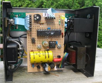
The
decimal shown at the right hand side of the display in the photo
indicates that the timer is on. When the preprogram is also active, two
decimals are shown.
Look for the preprogram tables in function set_current_programmed_on_off_times(), module appltimer.c.
There are four tables, ucOntimeHH, ucOntimeMM, ucOfftimeHH, and
ucOfftimeMM. Each table contains 52 entries, one for each week of the
year. Unless you live in Toronto, Ontario, the times in the tables are
not suitable for you and must be changed. I used the US Naval Observatory data services
to generate a chart of sunrise and sunset times for an entire year for
my location. I then used each 7th entry in the chart for my on and off
times table, with a small adjustment. I wanted the timer to turn on 10
to 15 minutes before sunset, and off 10 to 15 minutes after sunrise.
Keep in mind that the times change a bit in the course of a week,
and cloudy days appear to have less daylight than clear days. All
the times are in Standard Time; elsewhere the program checks
for Daylight Time and adjusts the hour as required. The program is
coded for Eastern Time; for other time zones a few more tweaks are
required in the code. You will then have to rebuild the project.
I used AVR Studio and WinAVR GCC,
both freely available. Create a project with my .c and .h files. Select
ATMega88 (or ATMega168) as the processor, and a clock frequency of 8
mHz, and build.
The
program stores important state variables in EEPROM, so that if powered
off for any reason, it will come back on in the same state. The RTC
remembers the date and time, as long as the battery is good, which
should be a few years.
Update
Nov. 1, 2012 - When setting the clock you set the date as well as the
time, so the RTC knows the date. (However there is no normal display of
the date.) I use the date to calculate when Daylight Savings Time (DST)
kickes in and out, in order to adjust the preprogram table
times so the relay turns on at the expected time. Later I realized
I could use that information to automatically adjust the clock so it
did not have to be done manually twice a year. It is hard coded for
Eastern Time, North America. If you implement this project elsewhere,
look at the code in the calendar.c routine and make the necessary
adjustments. DST is a big Pain in the Ass and in my opinion serves no
useful purpose except to confuse and inconvenience people, and
certainly makes this project needlessly complicated.
Download C
source code for the timer
Back
to VE3LNY's AVR Project Page