UC3906 SLA Battery Charger 2.5Amp
This project is a follow-on to my original SLA
charger project.
If you're not familiar with it, please have a look for the background
information. The UC3906 datasheet can be found here,
and the UC3906 application note here,
and VK3EM's project here.
(If the UC3906 links are broken, do a web search on UC3906.)
2020-08
Update: As interesting and useful as this project has been, there are
commercial products available today that are neater and cheaper than
projects like this. For example, the NOCO Genius series. I'm not throwing my chargers away but I probably wouldn't build another.
My 55 AH Gel-Cell battery finally packed it in
after more than
10 years. I credit its long life to my UC3906 charger. I
replaced the battery with a larger 100 AH deep-discharge marine SLA
battery. I wanted a charger with more oomph since the previous one was
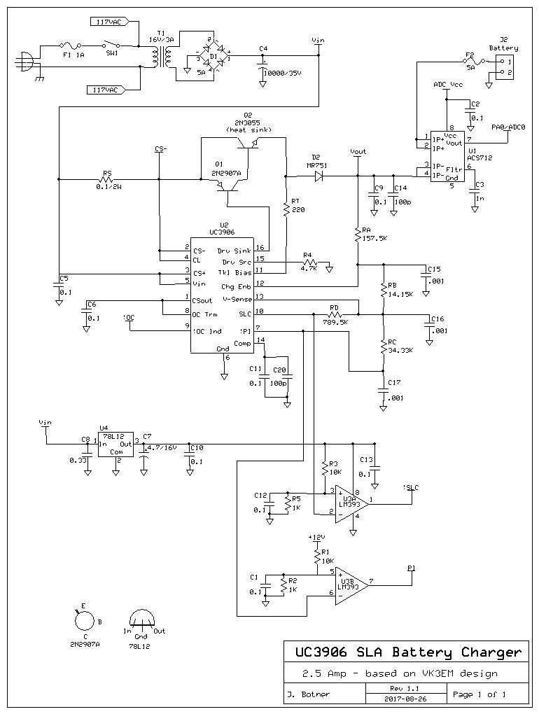
only 1 Amp. This one is good for 2.5 Amps. It is based on the same
UC3906 charger chip, with a beefier power supply and pass transistor.
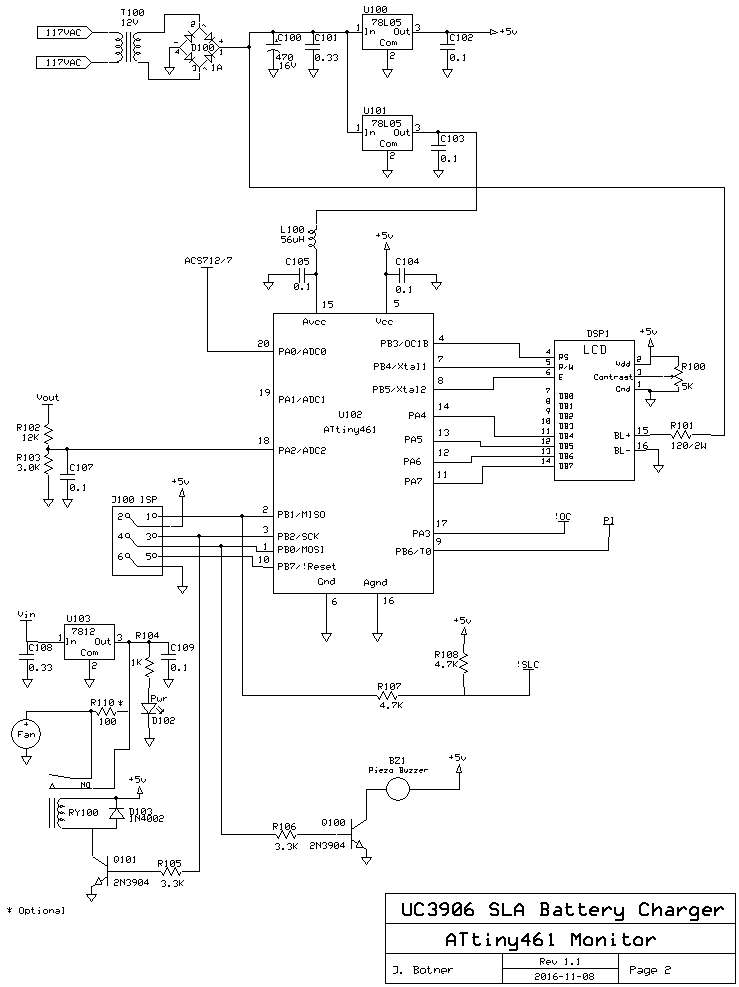
In addition, I added an ATtiny461A to monitor the state of the
charger.
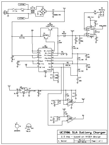
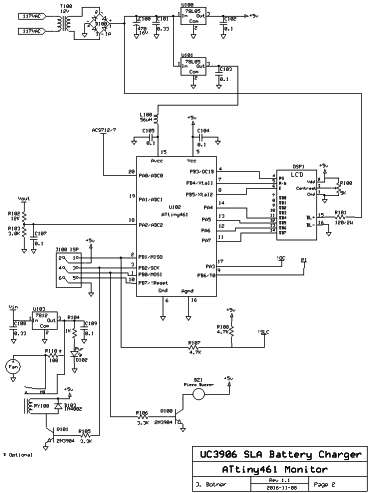
(Click to enlarge the schematics.)
I didn't really understand how VK3EM's monitoring
circuits
worked until I developed this project. The UC3906 doesn't specifically
provide
status information except for SLC (State Level Control, or float charge
mode) and Overcharge Indicate (OC), and even that
is not very useful. The UC3906 operates in three modes: bulk
charge, overcharge, and float charge. OC is sometimes
on for bulk mode, then on for
overcharge mode, then goes off. I wanted to display on
the LCD which state the charger was in. Having watched the charger
during a complete cycle, I have come to the following conclusion: In
bulk charge mode, OC may be on and SLC (state
level control) is off, and the current is at Imax. (Here I use logical
state, not actual state, since both indicators are
inverse
logic.) The charger goes into overcharge mode when the battery voltage
reaches 90% Voc. If OC was off it comes on. What happens is the
charge current starts to drop, maintaining the battery near Voc for a
period of time. After a while OC goes off and
SLC goes
on, and the charger enters float mode and maintains the battery at the
float charge voltage
Vf.
So
to know what state the charger is in you also need to know the charge
current. If OC is on, it may be in bulk or overcharge mode. If the
current is at or near Imax, it is in bulk charge mode. When the current
drops off, it is in overcharge mode. When SLC goes on (and OC off), the
battery is in float charge mode. You might also be able to distinguish
between bulk and overcharge mode by watching the battery voltage, if
you know what Voc is, but current is more useful.
VK3EM's project provides for an
LED to indicate float charge mode by monitoring SLC, which is fine as
long as everything is working right. I don't
agree with VK3EM's comment about the elevated charge
(overcharge) indicator circuit, that the OC pin changes state from bulk
to overcharge mode. I did not observe this consistently (although it
would have
been nice if it had). Interestingly his Elevated Charge circuit is 'not
fitted',
possibly because it didn't work as planned.
VK3EM's charge
current monitor circuit is of dubious value, as he documents in his
paper. Measuring tiny voltages across a small value resistor sitting at
the supply voltage rail is very difficult and even harder to interface
to a microprocessor. I decided to try a
different approach, to use a Hall-Effect current sensor from Sparkfun
Electronics,
p/n BOB-08882*.
This contains a ACS712
5 Amp Hall-effect
linear current sensor chip. The in-line resistance is almost
negligible, so I put it in the output line to the battery. It is
completely isolated from the circuit it is sampling, and it outputs
nominal 185mV/A which can be measured by the ATtiny861
A/D at ADC0 using the 2.56V internal reference voltage. The ACS712
is a bipolar sensor, and it needs a way to indicate both positive and
negative currents. It does this by outputting 2.5V (assuming Vcc is
5.0V) when the current is zero. Since I'm using 2.56V as Aref, I can't
allow the voltage to increase with increasing current, so I wired the
sensor the other way around, so the Vout decreases with increasing
current. In this application, Vout goes from 2.50 volts at no current
to around 2.0 volts at max current. There's no problem dealing with
this in the software. There are defines for Vcc and the sensor transfer
function ("Sens"), which can vary from 180 to 190 mV/A according to the
spec sheet. You can measure
AVcc, and infer Sens from the accuracy of the current display. Note
that the resolution of the A/D is not quite up to the job, so at the
low end the readout goes from 0mA to 16mA to 27mA etc., but it's good
enough for this project.
* Sparkfun has another version of the ACS712, with
an op-amp built in, p/n SEN-08883, I
didn't use this part, please don't confuse them.
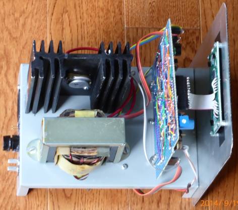
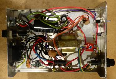
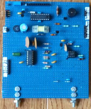
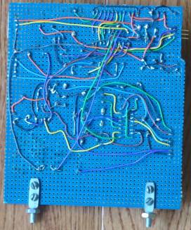
(Sorry
about the messy build. I usually don't plan things in much detail,
except to ensure all the parts will fit somewhere, and the front panel
looks decent. The case comes from a fleamarket minus the front panel
and
chassis, which I provided from my scrap bin.) You can see the ACS712
breakout in the right photo, on the right-hand side, wired between the
fuse holder and the wire going to the output connector.
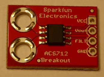 The ACS712 Hall-effect current sensor module.
You should go over the calculations for 6 of the resistors
that control the UC3906 as per the spec sheet. (Perhaps your
battery requires a different float charge voltage, or you want a
different Voc.) After tediously doing this
a few times I finally wrote
this program
to
make it easier. The oddball resistance values for RA..RD can be
achieved by
placing two measured resistors in series. (Or parallel if you prefer.)
I use one
larger value close to the required resistance, then find a smaller
value resistor to make up the difference. Here are the parameters I
used and the calculated resistors:
| Id |
67 mA |
| Vf |
13.8
V |
| Voc |
14.3
V |
| Imax |
2.5 A |
| Vt |
10 V |
| It |
25 mA |
| Vin |
18 V |
| RA |
157.5K |
| RB |
14.15K |
| RC |
34.3K |
| RD |
789.5K |
| RS |
0.1 |
| RT |
220 |
RS
must be a 2W resistor, as it dissipates 0.6W or so. Use a 1%
resistor if you can, or a selected close value, since it controls the
charge current Imax.
Update - I have found that after calculating for a Vfloat of 13.8V,
the circuit actually provides a Vfloat closer to 13.6V. This is not a
problem, but if you are a perfectionist, you can take this into account
during the design stage and hopefully it will come out better.
It
is important in a project like this to build for the high current
sections. Keep in mind that the UC3906 monitors the battery voltage
inside the charger box, but the actual battery voltage at the end of a
cable may be different. Use heavy duty connectors and cable (and fuse
holder). A 0.5 ohm resistance in the path drops 1.25 Volts (!) at 2.5A,
which will throw off the UC3906 parameters quite a bit.
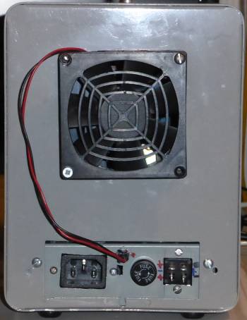
Select a good transformer for T1 (at least 3A) and heatsink
for Q2,
because it might run at Imax for a long time. I placed a 3 inch computer
fan on
the back of the cabinet, controlled by the microprocessor. The ATtiny461
has an onboard temperature sensor, so the fan is turned on either when
the current or the temperature is high enough.
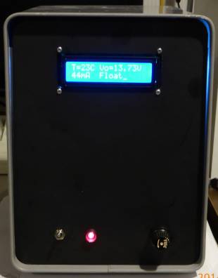
The
ATtiny461 software is programmed to monitor the state of the charger
and report as much information as possible on the LCD. On line 1 it
shows the temperature and Vout. On line 2 it shows charge current and
the charger state. It tries to detect failure modes such as those
documented in my original SLA
charger project. When a fault is detected the beeper is
sounded and a message is displayed in place of the charger state, as
follows:
| Fault PI |
The UC3906 PI (Power Indicate) status is off.
Possible failed UC3906 or power supply. |
| Fault TM |
Charger has been in bulk (or over) charge for too long.
May indicate a bad battery. |
| Fault VO |
Charger
is in Float mode but Vout is too low. May indicate a failed UC3906. |
O=x SL=x
|
"Unknown
state" which my routine determine_state has not accounted for. For
example, when OC=0, SLC=1 which indicates float charge but the current
is too high.
|
Update
2016-07-25 I discovered a problem in the fault message handling and a
buffer overflow bug, and reworked some of the code.
When
a fault occurs the beeper sounds and the short message is displayed on
line 2. The fault will reset in 6 seconds and the program will carry
on. (Keep in mind that the UC3906 is not affected by this program, only
monitored. The only way to affect the UC3906 is to power cycle the
project.) If it is a hard fault it will re-occur, so the message will
stay on the display (and the beeper will keep sounding). I
have not been able to thoroughly test these fault modes so
far, so there is no assurance that they work. There are some defines in
main.c that specify the voltage and time for these failures you may
want to review. In any case a look at the display should tell you what
the charger is doing and if everything is OK.
2015-09
Update I realized that an ATtiny861 was not required and replaced it
with an ATtiny461A. The thermometer required recalibration, otherwise
no issues. The schematic still shows ATtiny861, however.
2016-11
Update. My unit started faulting and gave me the opportunity to look at
the fault handling code again. I reorganized the logic and made what I
hope are a few improvements.
Footnote. Greg, ZL2BZH, makes
the following observation: "One thing that can have an effect on the
project’s success is to remember that the IC tracks the ambient
temperature to adjust the reference voltage, to follow the necessary
voltages for lead acid cells at different temperatures. So it is
desirable to keep the IC away from any heat producing components."
Many thanks, Greg.
Further, I added R110 to
make the fan run slowly all the time to counter the small heat build-up
in the case during float charge.
Download WinAVR C
source code for the charger monitor
Back
to VE3LNY's AVR Projects Page