VE3EG/VE3HHT
The Amateur Radio Website of Keith Thomson
White Box 10GHz Transverter
A number of ham radio operators have made their start on the 10 GHz amateur band using commercial-surplus microwave transceivers made by M/A-Com. These units were originally built in white-painted metal enclosures and are known as "White Boxes". They can be modified to operate as transverters (transceiving converters) to convert the signals from an amateur VHF transceiver to the amateur 10 GHz band. The VHF transceiver is known as the intermediate frequency (IF) transceiver in this application.
Modifying a White Box for ham radio service usually involves removing the equipment from the box and keeping just the main tray containing the desired parts. My White Box had been partly modified by the late Dr. Arthur Schulman, VE3ZV for use by Steve, VE3TFU. Steve generously gave it to me, and another Steve, VE3SMA kindly completed the modifications to the RF circuitry before I received the unit. Steve has modified other White Boxes and his paper describing the process is on the Downloads page of this website. For my White Box, he removed the receive filter in the transverter module and added a new receive connector but otherwise followed the procedure in his paper.
The main parts of use in ham service are the RF unit, the local oscillator (LO) unit and the linear regulator board as shown in Figure 1, a photo of the unit as Steve received it. I had to do the following things in order to get it on the air :
- tidy the DC wiring and improve the distribution, switching and fusing
- add a power cable and fuse for the IF transceiver
- add IF switching and control and sequencing circuitry
- add a radio frequency (RF) relay and antenna
My goals were to keep the wiring within the White Box simple, to make it easy to build. To make it easy to operate, I wanted to make the external control, DC and RF wiring simple as well. As a result, I decided to design a printed circuit board for the control and sequencing. Designing the pcb to handle much of the internal and external interconnection allowed me to fit all the circuitry and wiring in the space available on the White Box tray. The circuitry was designed to work with a Yaesu FT-817 as the IF transceiver.
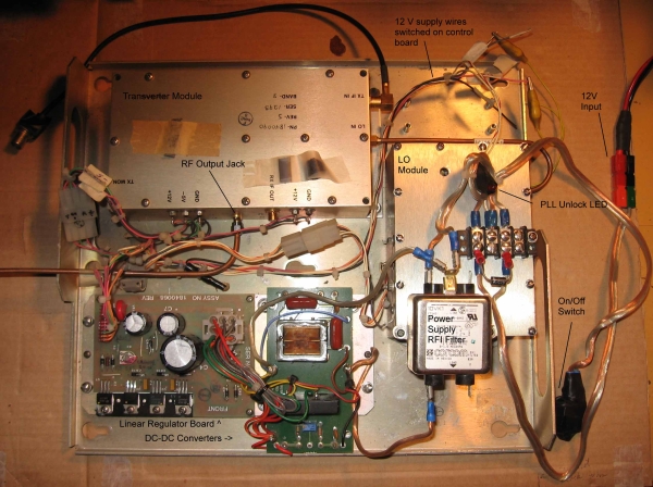
Figure 1. Here's my White Box when Steve, VE3SMA started working on it.
DC Distribution
The White Box was originally designed to work in a fixed location, with an AC power supply providing several different supply and bias voltages. Since the ham radio version is generally used for portable operation with battery power, Arthur had added two DC-to-DC converters to create the necessary supply and bias voltages from the battery voltage.
I used some perf board to re-mount the -5 v bias supply and added DC distribution terminal blocks. The tray handle seemed like a good location for switches and connectors, so I installed the power switch, the IF connector and a panel to hold the fuseholders for the transverter and the IF transceiver.
Power for the IF Transceiver
To make system setup easier and to keep the operating area as uncluttered as possible, I powered the IF transceiver from the White Box, with a fuse, polarity protection diode and power cable from the DC distribution board.
Control and Sequencing Circuitry
An interface is required between the IF transceiver and the transverter to switch the IF signals between the transmit and receive portions of the transverter and to control the operation of the White Box. Switching of the power, IF, and transmit and receive signals must be carefully sequenced in order to avoid damage to the circuitry of the transverter. This circuitry must detect whether the IF transceiver is in transmit or receive and:
On transmit:
- the transmit section of the transverter must be powered (but only if the -5 v bias is present)
- the transmit output of the transverter must be connected to the antenna
- the transmit signal from the IF transceiver must be attenuated and connected to the transmit IF input of the transverter
On receive:
- the receive section of the transverter must be powered
- the antenna must be connected to the receive input of the transverter
- the receive IF output of the transverter must be amplified and connected to the receive input of the IF transceiver
As described in his paper, Steve, VE3SMA had developed circuitry for switching and control while modifying another White Box. I used his circuitry as a basis for mine. See Figure 2 for the Control Board schematic.
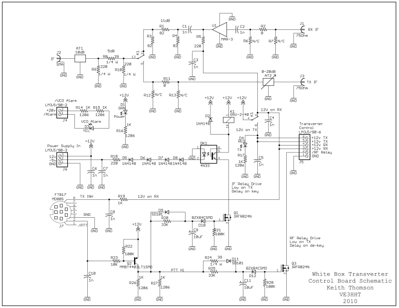
Figure 2. The Control Board Schematic.
The Control Board installed in the White Box is shown in Figure 3.
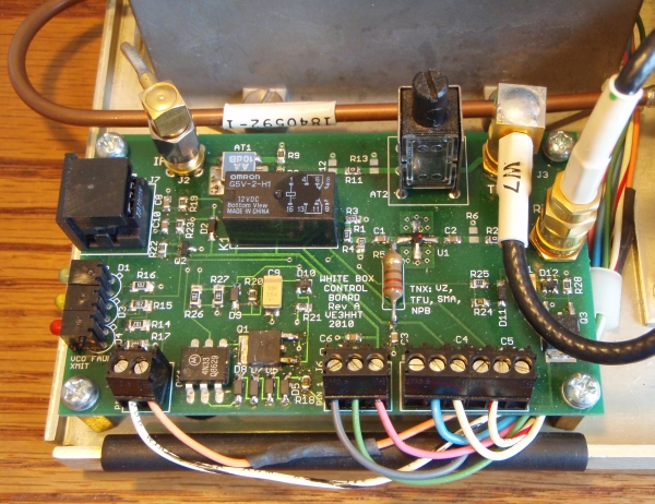
Figure 3. The Control Board.
The sequencing of the transverter must take into account the characteristics of the RF relay used to switch the transmit and receive signals to the antenna:
- because the RF relay contacts are not built to switch while transmit signals are present, the relay must switch while no RF is present. This entails switching it instantly when going into transmit, before any RF is present, and waiting briefly before switching it when returning to receive. The brief delay allows the transmitter output to dissipate.
- while the RF relay is switching, the isolation between the receive contact and the transmit contact is reduced. If there are transmit signals present during the switch, the receiver input can see potentially damaging signal levels. To ensure the receive input stage does not see damaging signals, make sure there is no transmit RF present before switching the RF relay to receive.
- because the RF relay contacts do not switch instantly, ensure there is a good transmit path before turning on the transmitter. Before the transmitter produces any RF, the path to the antenna must be complete. This saves both the RF relay and the transmitter.
The sequencer must also ensure that the IF transceiver cannot damage the input of the transverter by transmitting while the transverter is in receive. This could happen if a control cable is unplugged, or if there is a component failure in the control circuitry.
Steve had designed the control circuitry to work with the FT-817 transmit output set to 1 watt. He also built in enough attenuation that nothing would be damaged if the FT-817 was set to transmit at 5 watts by mistake. I used a pcb-mount attenuator to handle the transmit power of the FT-817 in either case. I also used the Transmit Inhibit input of the FT-817 IF transceiver, just in case. The sequence of events became:
On going into transmit:
- instantly power the RF relay
- after a short delay, switch DC and IF signals to the transmitter and remove the FT817 Transmit Inhibit
On returning to receive:
- instantly inhibit the FT817 and switch DC and IF signals to the receiver
- after a short delay, turn off the RF relay
To control the sequencing, I used circuitry similar to that in my DB6NT SEQ2 sequencer ( https://shop.kuhne-electronic.com/kuhne/en/). Additional circuitry on the board:
- provides the Transmit Inhibit signal to the IF transceiver until the White Box is ready to transmit
- inhibits changing to transmit if the -5 volt bias for the transmitter FETs is absent
- indicates an alarm condition from the White Box local oscillator module
I used the free version of the Cadsoft Eagle software package for the schematic capture and pc board layout.
RF Relay and Antenna
For the initial contacts the antenna would be a horn, mounted on the White Box. An RF relay is needed to switch the antenna between the transmitter and the receiver.
The White Box could be improved by replacing the horn antenna with an external antenna with more gain, and adding amplifiers to improve the receive sensitivity and to increase the power of the transmit signal. In the short term, space was needed for the relay and the antenna and in the longer term, space would be needed for the relay and amplifiers, so I installed a "mezzanine" panel which I hoped would be big enough to take any future amplifiers and related filters. This panel mounts above the linear regulator board and the 12 volt DC-DC converter.
The horn antenna was connected to the relay with a short length of waveguide and a coax-to-waveguide transition. The length of waveguide was held in a mounting bracket and allowed easy changing of the horn. See Figure 4.
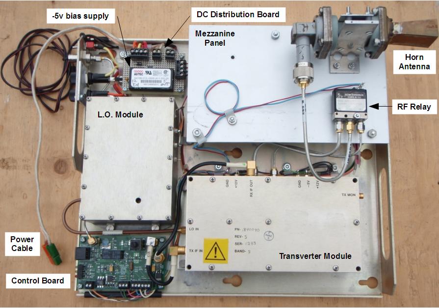
Figure 4. Here's my White Box when I was finished working on it (for the first time).
The complete system with IF transceiver, key and battery is shown in Figure 5.
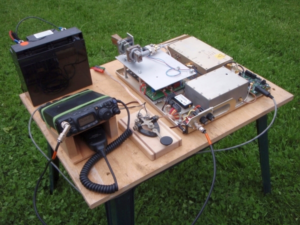
Figure 5. The complete White Box system, ready to communicate.
First Use
I tested the system with Steve, VE3SMA. You can see it in Figure 6 in a typical setup on the car roof. Not quite as neat as the posed setup in Figure 5! I then took the White Box out for the simultaneous SBMS and Spring Sprint 2010 contests. With a larger horn than shown in the pictures I was able to make 100 km contacts and had a lot of fun.
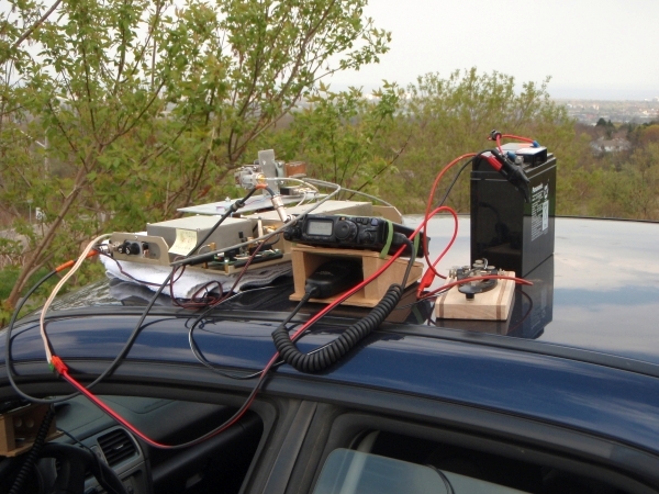
Figure 6. The system at its first field trial.
The first day of operation with the system showed two areas that need improvement (but what project ever worked properly first time!):
- strain relief for the control cable from the IF Transceiver. As the day went on, the control cable connection to the White Box became intermittent, apparently due to stress on the mini-DIN connector on the control board. Better strain relief for the cable was required, and possibly changing the connector to a bulkhead-mount style with wires to the board.
- frequency stability. On switching from transmit to receive I would find the other station had apparently moved in frequency. I suspected the voltage regulation to the local oscillator module needed attention.
Further Use
Further use of the White Box has been a lot of fun, including a rain scatter contact and causing a pileup across Lake Erie.
I have found that the mini-DIN connector on the control board does not make very reliable connection with the connector on the control cable, despite both pieces being made by the same manufacturer. Better strain relief would definitely help, and mechanical protection is definitely necessary as I found out when I overstressed the connector in the 2016 contest.
Temperature stability is not much of an issue after the crystal oven warms up, although the unit has shown some instability on transmit. I put thermal insulation around the oven to help with stability, warmup time and current draw.
After one season of operation of the White Box, I purchased a crystal for the local oscillator to allow operation with low-side injection. The modifications entailed are described on my White Box Local Oscillator page.
Dish and LNA
In 2013, I purchased a parabolic dish antenna and feed at the Dayton Hamvention. I installed the dish on the White Box chassis, using some sheet aluminum. I also bought a work stand for my woodworking hobby, expecting that it would be useful for ham radio projects. Initially, it made a good base for the White Box, much better than the car roof. Unfortunately, rotating the top section of the stand when turning the White Box wore out the clamp that holds the stand at the desired height, so I have developed a simple panning arrangment on a surveyor's tripod instead. In Figure 7, you can see the system with the added dish, on the work stand in the late afternoon in Prince Edward County, FN13.
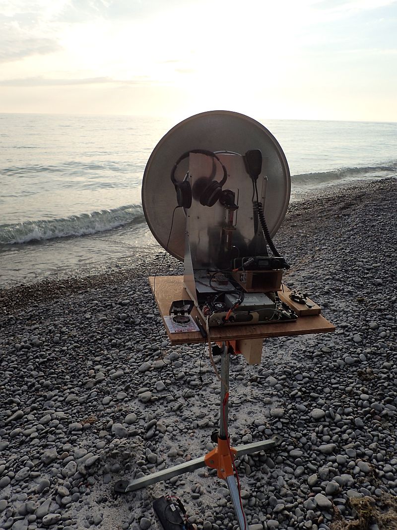
Figure 7. The system with the dish added.
After installing the dish, I purchased a blank PCB and parts kit for a low-noise amplifier (LNA) designed by Graham, VK3XDK. I assembled the board and built an enclosure from sheet brass and pcb material. See Figure 8. The two-stage LNA was predictably unstable in the enclosure. Emerson and Cuming GDS/SS-6M absorber inside the lid effectively cured the instability.
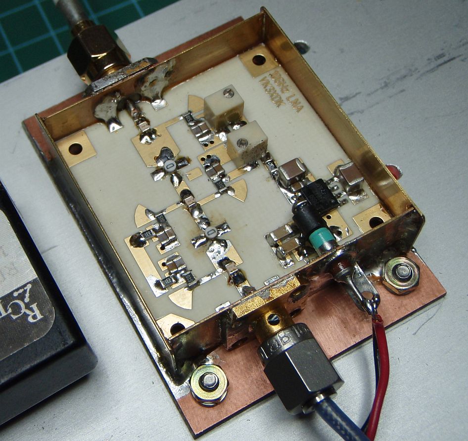
Figure 8. Inside the LNA.
With my test equipment, I measured the LNA gain to be 19dB. At the NEWSVHF Conference in 2014, Greg Bonaguide of Rohde & Schwarz was kind enough to measure the amplifier and found a gain of 20dB. This showed that my test equipment is reasonably accurate. Greg also measured a noise figure of 1.4dB, which is a little higher than I had hoped for, but still a big improvement over the system performance without an LNA. I used some of his equipment to tune up the original 6-pole receive filter from the White Box to make an image filter and installed it after the LNA. See Figure 9.
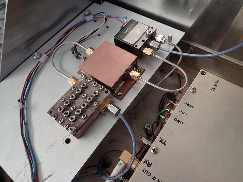
Figure 9. The LNA and image filter.
Operating with the White Box with the added gain of the dish and LNA was much more fun, as you would expect.
The White Box was never totally reliable, and the transmit power output seemed to be dropping. In 2018, I replaced the White Box with a DB6NT G3 transverter, and added a GPSDO a year later. This improved the power output, frequency stability and accuracy which made operating much easier, and more fun. I also added a surveyor's tripod, and a pan-and-tilt mechanism to make operating easier.
In 2021, I added a DB6NT 2W power amplifier.
The GPSDO was quick to lock and took very little current, but its output at 10MHz was just below the lower limit of the transverter specification. As a result, the transverter would lose lock at low supply voltages. In 2022, I replaced the GPSDO with an OCXO which draws more current but puts out more power at 10MHz. I also replaced the FT-817 with an IC-705. The FT-817 is a great IF radio, but the panoramic display of the IC-705 makes a big difference in finding signals on the band.
Copyright Keith Thomson, 2022.