NOT TO BE PUBLISHED
The information given in this document is not to be communicated either directly or
indirectly, to the Press or to any other person
not holding an official position in His Majesty's Service
WORKING
INSTRUCTIONS
Approved by the Chief of the General Staff, Department of National Defence, Ottawa.
INTRODUCTION:
This area consists of a scan of the entire Working Instructions for the Canadian WS#19 Mark III. Simply click on the thumbnail to see a larger photo.
Some of the pages are larger files than others, meaning it will take longer for them to load. I apologize to dial-up internet users (having been one myself until recently) but I have made every effort to make the files as small as possible without making them impossible or difficult to read.
While it would have been great for you, the viewer, had the Mk III Working Instructions been re-typed by hand, as was the case for the Mk II, the simple fact of time and labour no longer makes that possible.
It is appreciated that some scans, because they of necessity have been turned sideways, might cause some challenges in reading. However, in those cases it is suggested that you save that file to your own disk or hard drive and then open it using your computer's "Image Viewer". That utility will allow you to rotate the page for normal reading. It will also allow you to zoom in on the page, making it larger. How? When viewing your file directory, right click on the file name, place your cursor over "Open With" (click it if necessary) then when the menu appears click on (open) "Image Viewer", at least that's the way it works for me when using Microsoft stuff.
We hope to add more actual photographs of the Mk III, for technical assistance, as time goes by. If anyone reading this has such photos to contribute, we would be most happy to receive them for consideration to posting here. Credit will be given. The same goes for any modifications, schematics, etc, which might be helpful to those who are delving into the wonders of this fantastic radio. I say "fantastic" because in truth the 19 was years ahead of its time. For example, just look at how much longer it took for Amateur Radio to adopt the transceiver model.
Errors or problems in opening any thumbnail, other than download time for dial-up, or in any text on this page, should be reported to ve3bdb (at) sympatico. Please provide full details. Be sure to replace the "(at)" with the symbol @ when addressing the email.
THE SCANS:
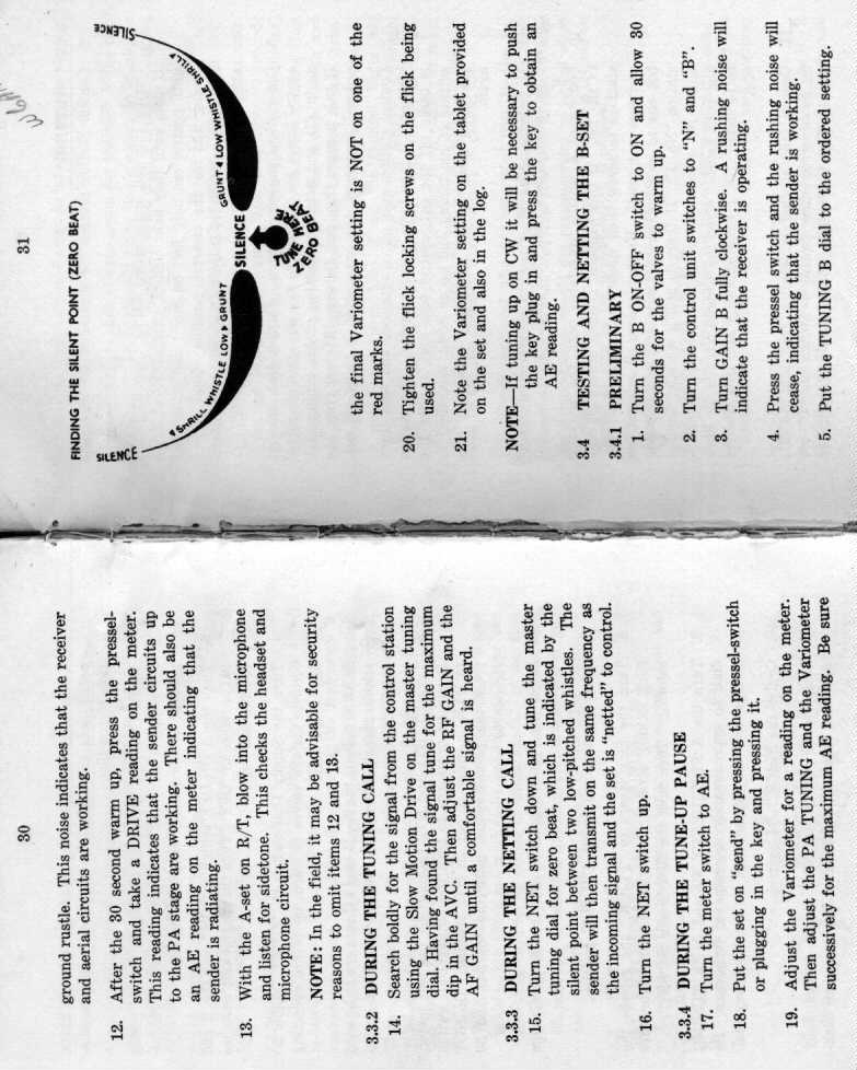
As a general guide to what's where, following is a brief overview of what to expect in the scans, according to Chapter, Appendix, Table, Photo and Fig. For a detailed description of contents, reading the "Contents" scans will be of great assistance as each scan includes the actual page number(s). Note that where a page number seems to be missing it's because that page is left blank in the actual manual -- i.e. pages 2, 110, 116 and 118 are blank and unnumbered but are counted in the total number of pages. Where a page number seems to be repeated in the scans it's simply because that page contains two different categories of information and thus overlap. Page 1 was not scanned but its contents are reprinted in red and blue at the top of this page, including the wartime "Not to be Published" admonition..
Title Summary of Contents
Cover: self explanatory
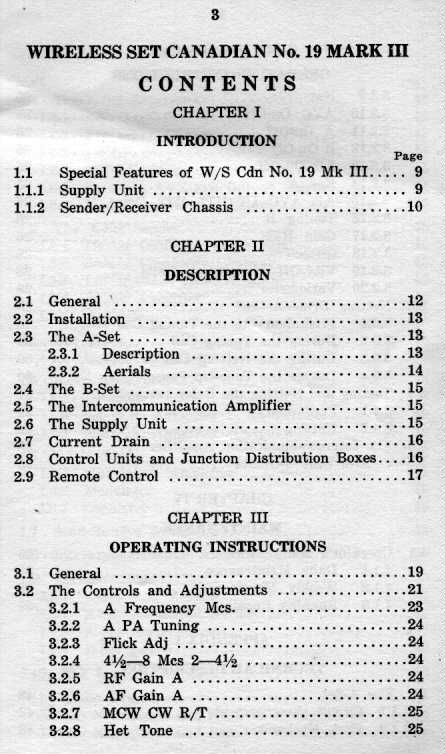
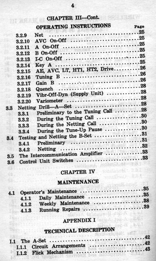
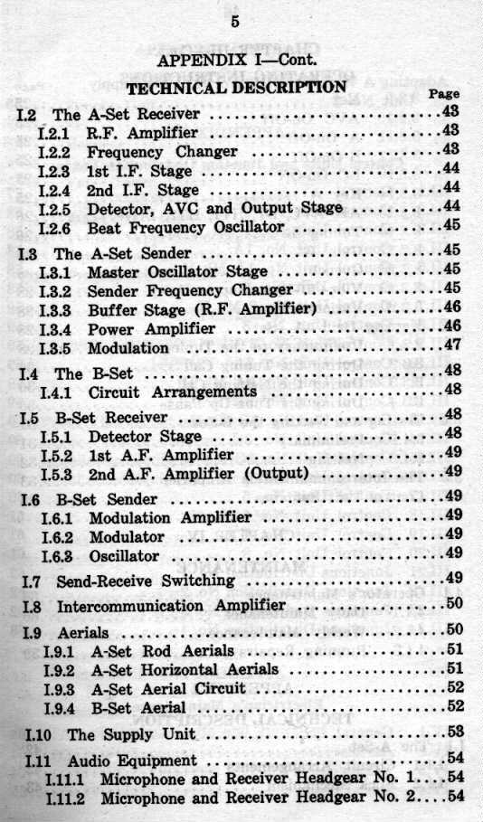
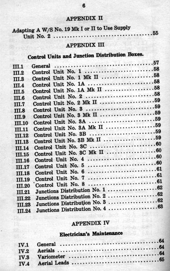
Contents Pages 1 to 6 inclusive: self explanatory
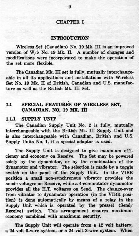
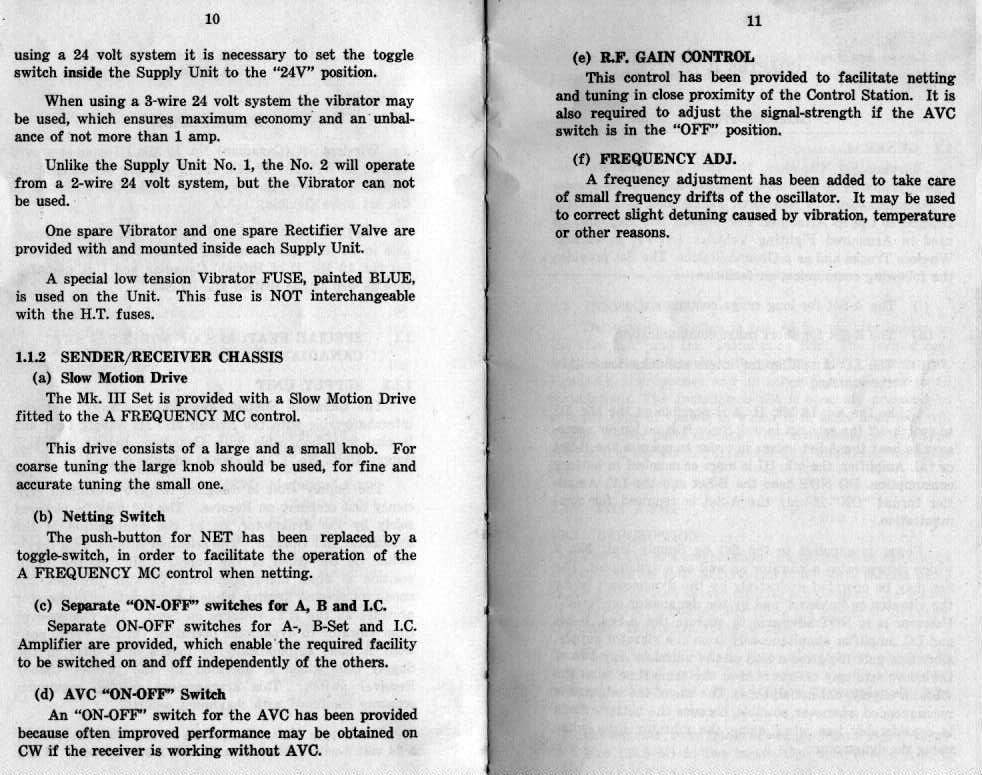
Chapter I: Introduction to the manual as well as on overview of the set's "special features" improvements over the Mk II, including supply unit, slow motion drive, netting switch, separate A, B and IC switches, AVC switch, RF gain control and frequency adjustment.
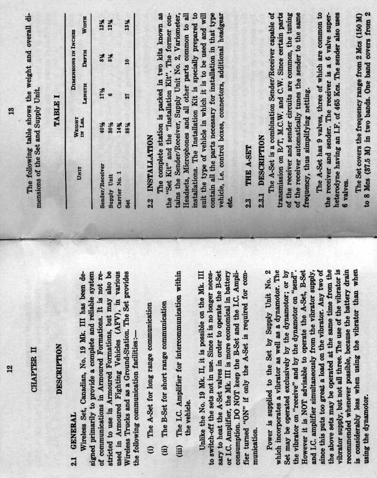
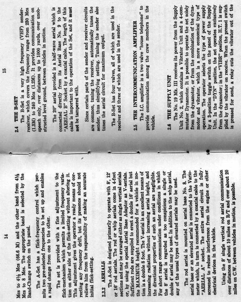
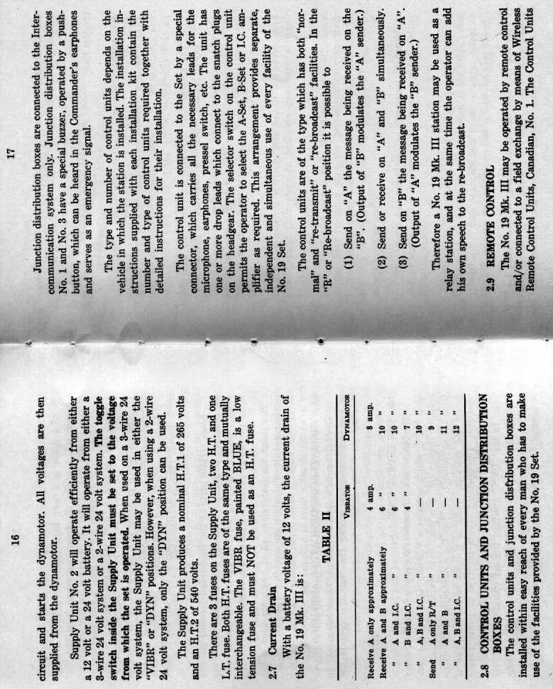
Chapter II: Description of the Mk III, including weights, A & B sets and the IC, aerials, supply unit, Table II, control units and boxes, remote control and a WARNING .
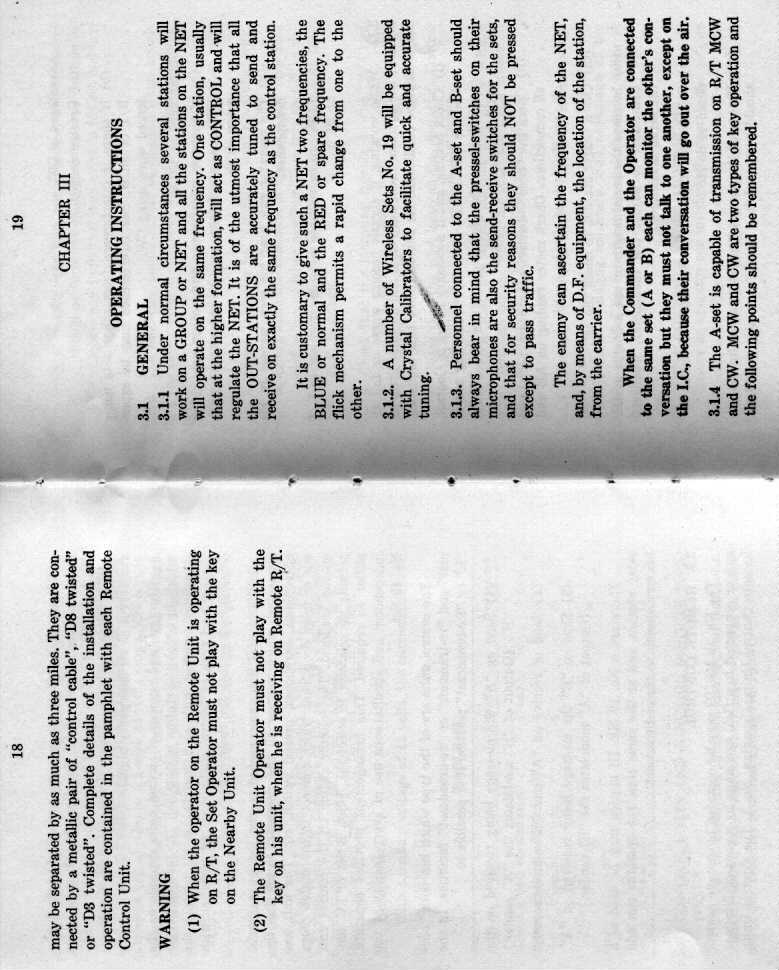
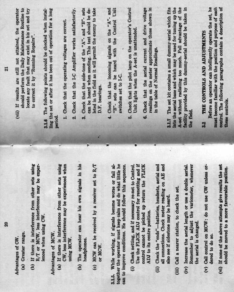
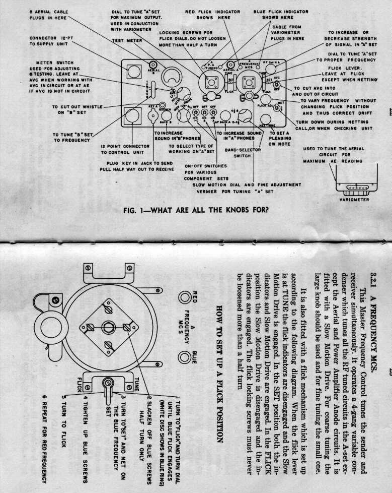
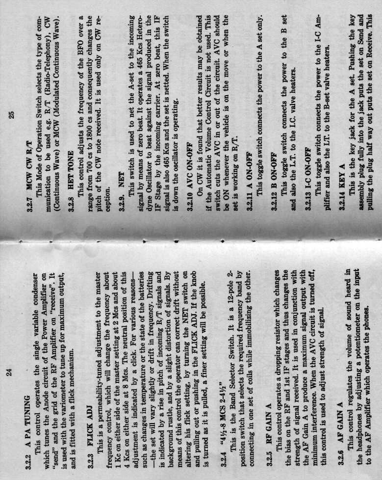
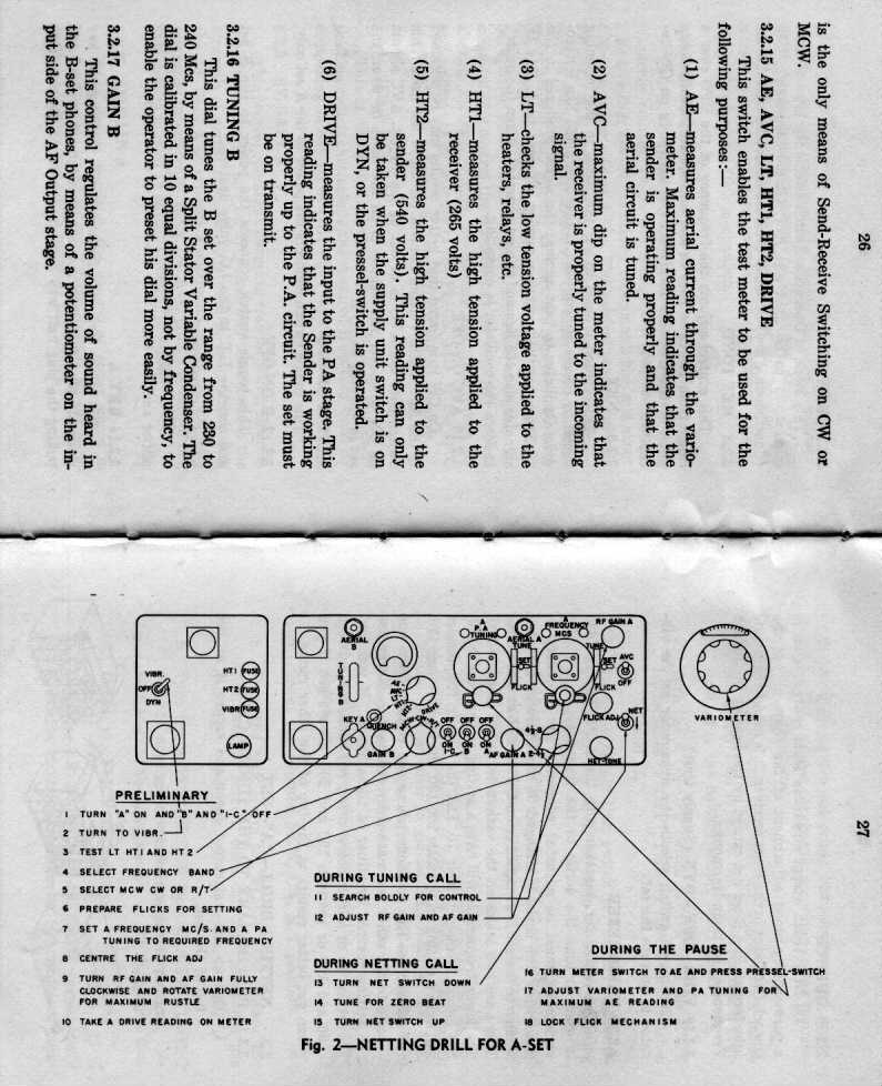
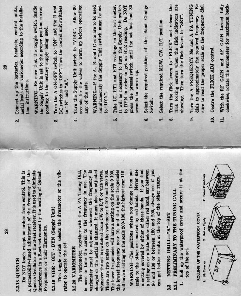
Chapter III: Operating instructions, Fig. 1 "What are all the knobs for?" and how to use them all, Fig 2 "Netting Drill for A Set", rolling up the water proof cover, Quench adjustment, etc.
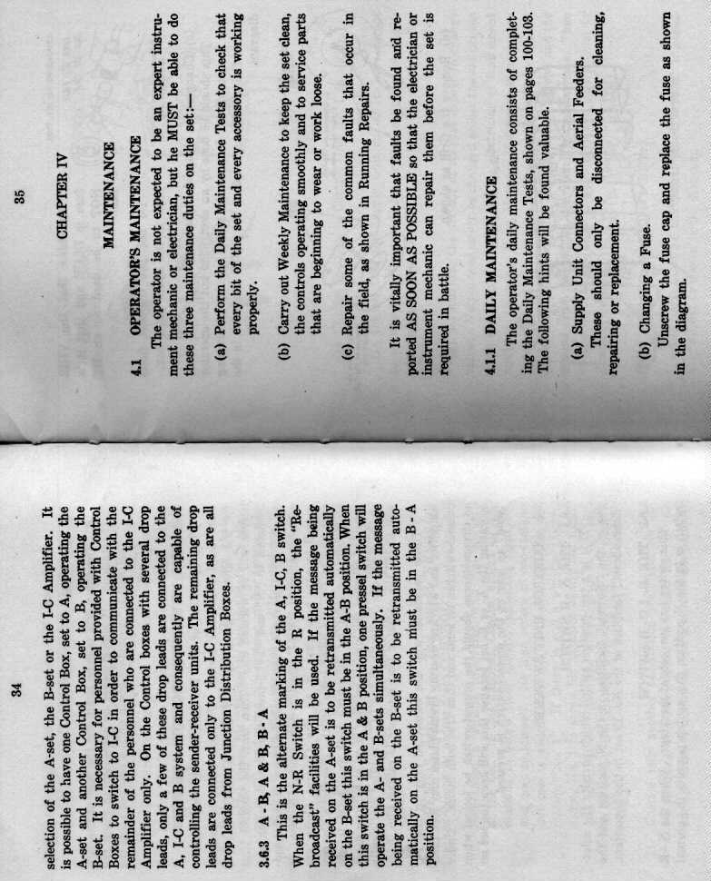
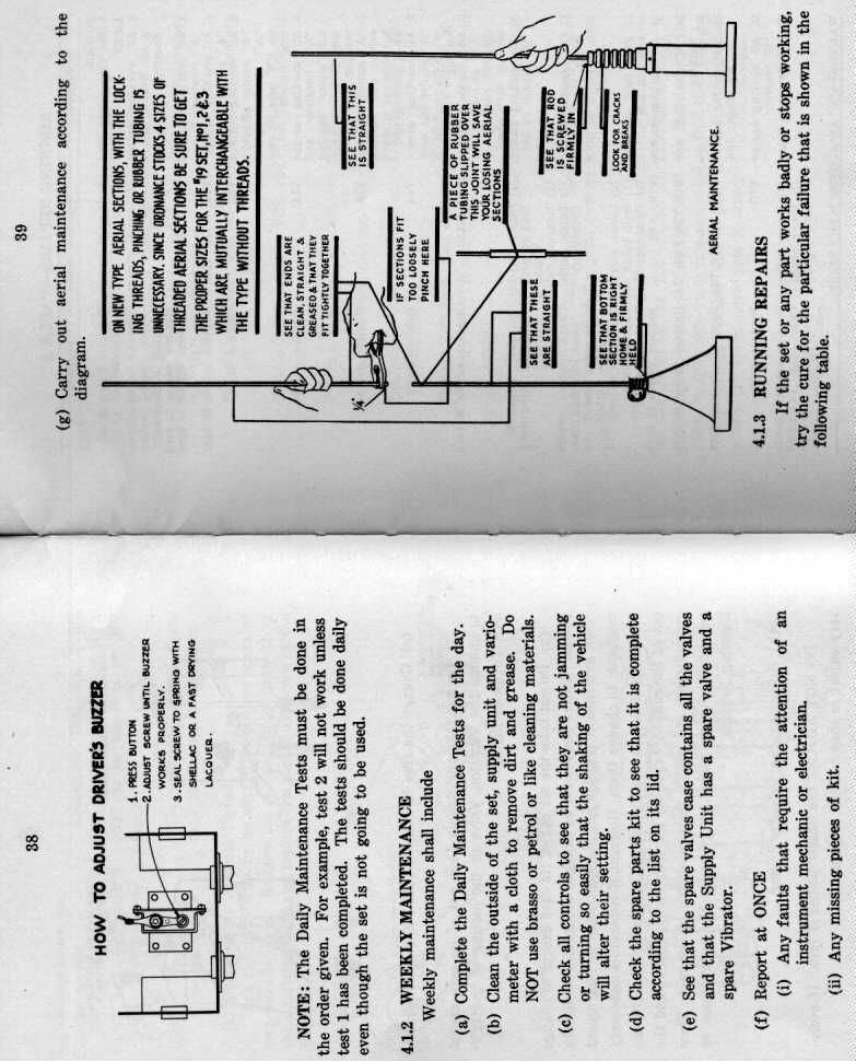
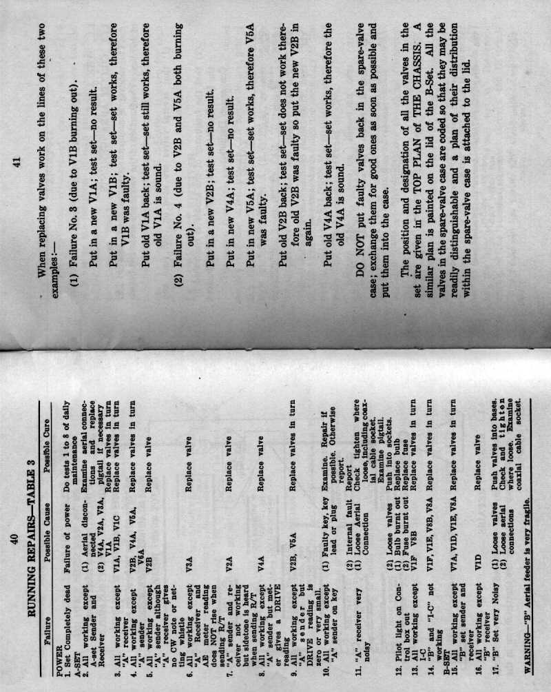
Chapter IV: Maintenance, including operator's maintenance, daily maintenance, changing fuses, changing A set aerial pig tail, removing the grill (brush guard), weekly maintenance, aerial maintenance, Table 3 "Running Repairs", etc.
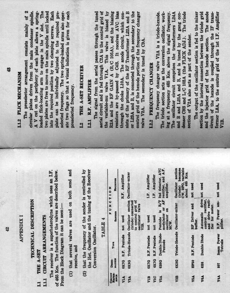
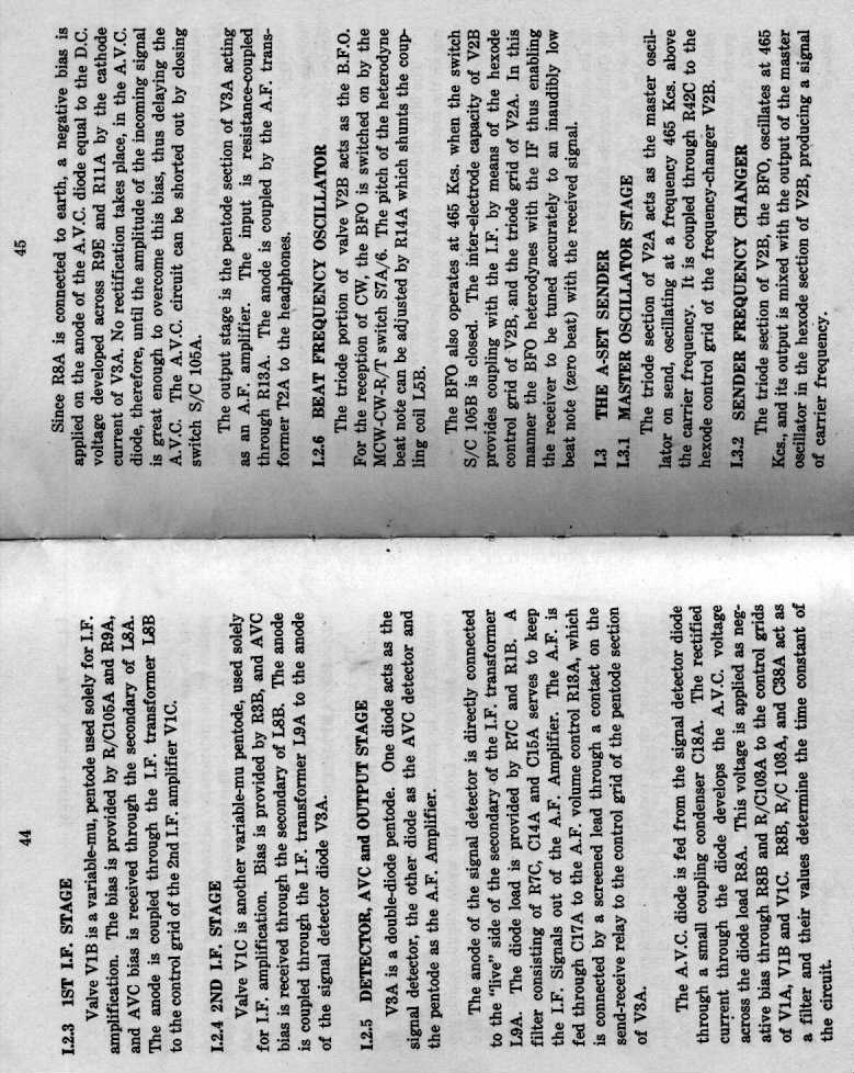
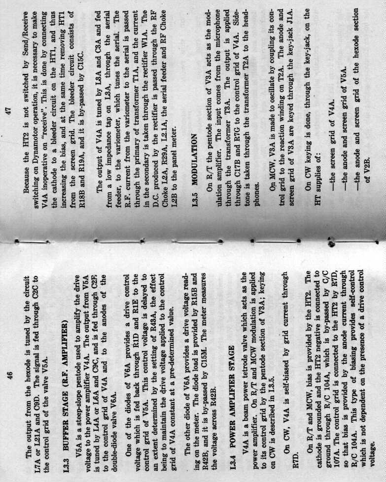
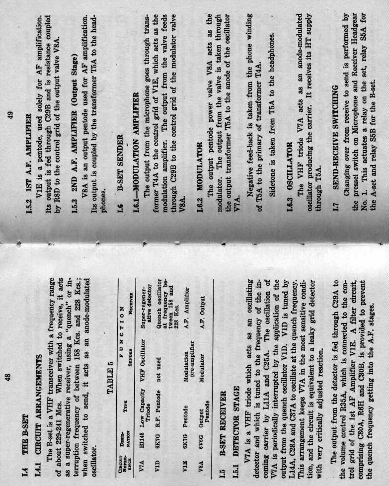
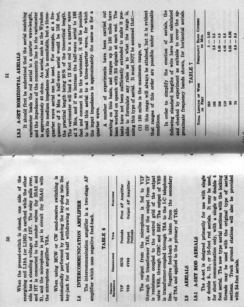
Appendix I: Technical Description, including circuit arrangements, flick mechanism, A set receiver and its RF amplifier, frequency changer, 1st IF stage, 2nd IF stage, detector, AVC and output stage, BFO; also A set sender and its master oscillator stage, sender frequency changer, buffer stage (RF amplifier), power amplifier stage, modulation; also B set circuit arrangements and B set receiver's detector stage, 1st AF amplifier, 2nd AF amplifier (output stage); also B set sender's modulation amplifier, modulator, oscillator, send/receive switching; also intercommunication amplifier and Table 6 of valves; also A set rod aerials and horizontal aerials and Table 7 of horizontal , aerial lengths, A set aerial circuit, B set aerial; also Supply Unit No. 1; also audio equipment (microphone and receiver headgear Nos. 1 and 2.
Appendix II: Adapting a Mk I or Mk II to use Supply Unit #2, wiring changes and a WARNING.
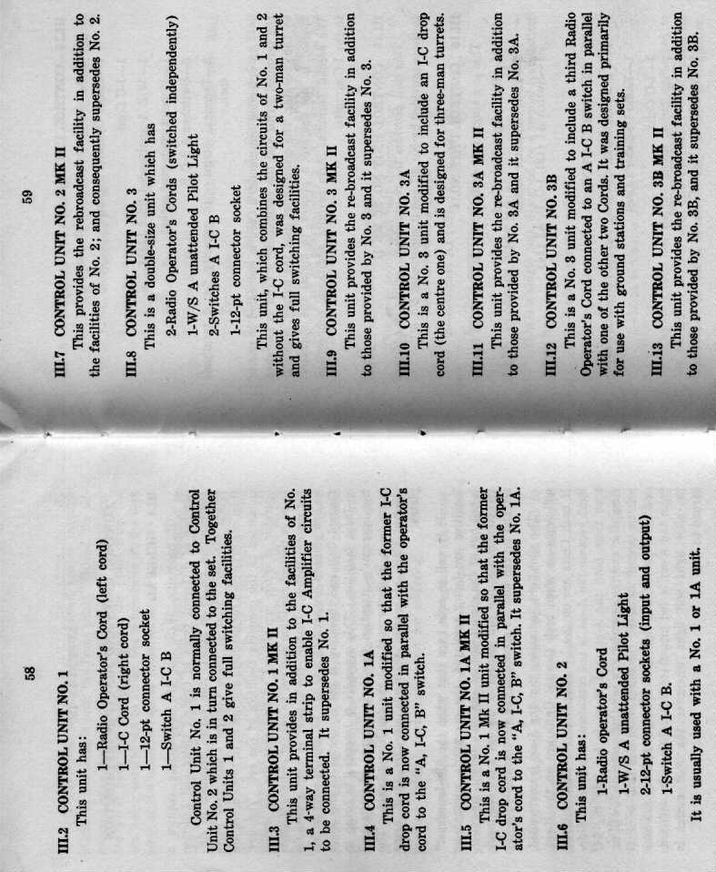
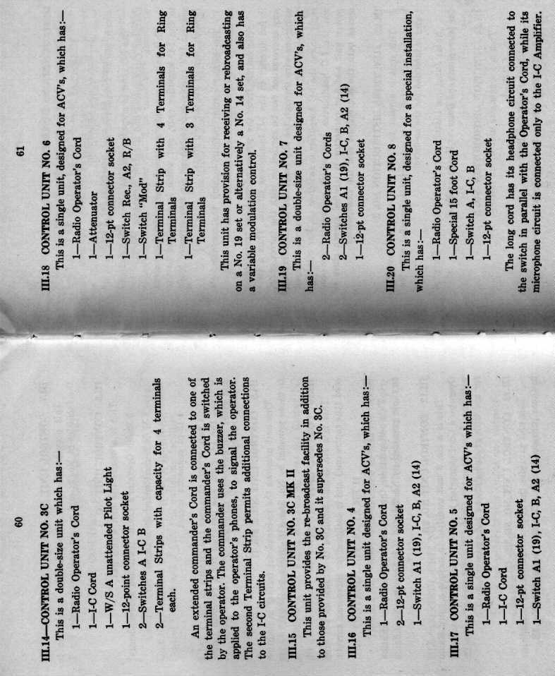
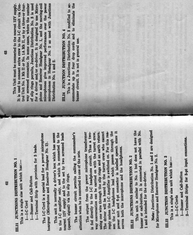
Appendix III: Control units and junction distribution boxes, including extensive information about all of those items, which number nineteen of the former and four of the latter! (How the heck did they ever keep track of them all??)
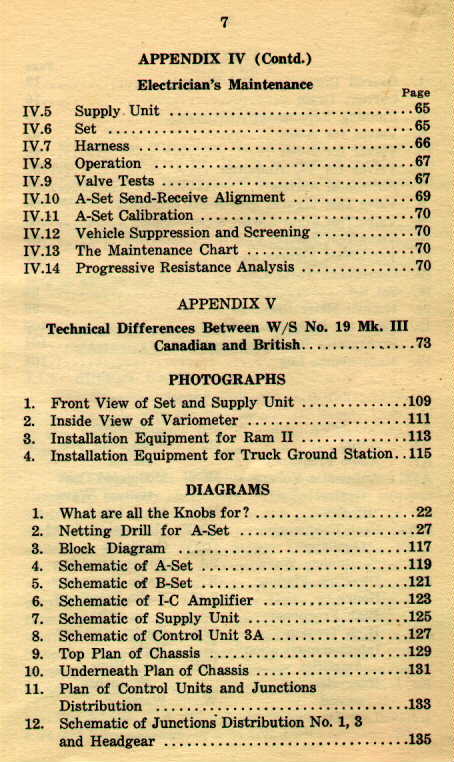
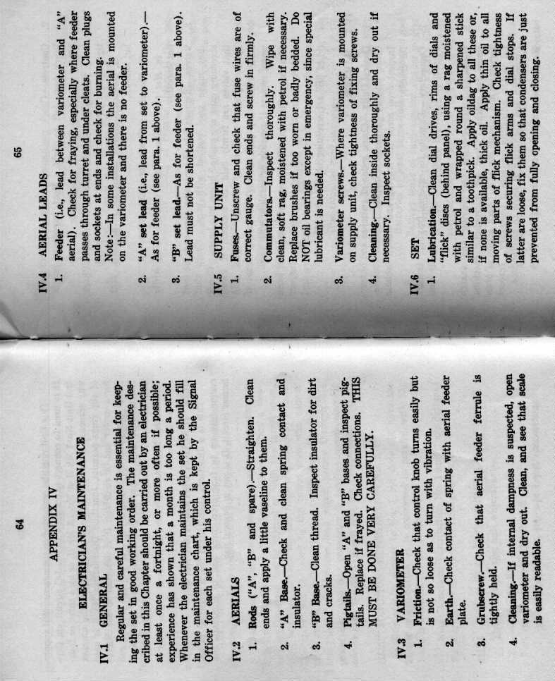
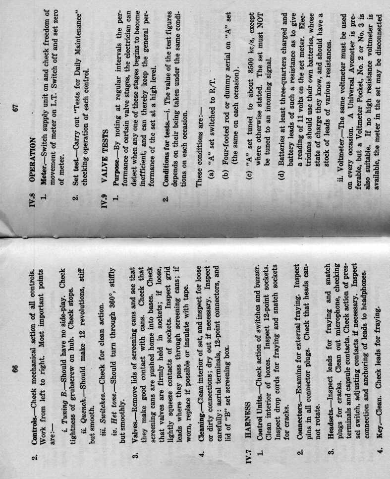
Appendix IV: Electrician's Maintenance, including aerials, variometer, aerial leads, supply unit, "set" mechanism, controls, valves, cleaning; also harnesses for control units, connectors, headsets, key; also operation including meter and "set" test; also valve tests, Tables 8, 9, 10 and 11 which all concern optimum readings for A and B set sender and receiver, sender/receiver alignment and calibration, suppression and screening, resistance analysis.
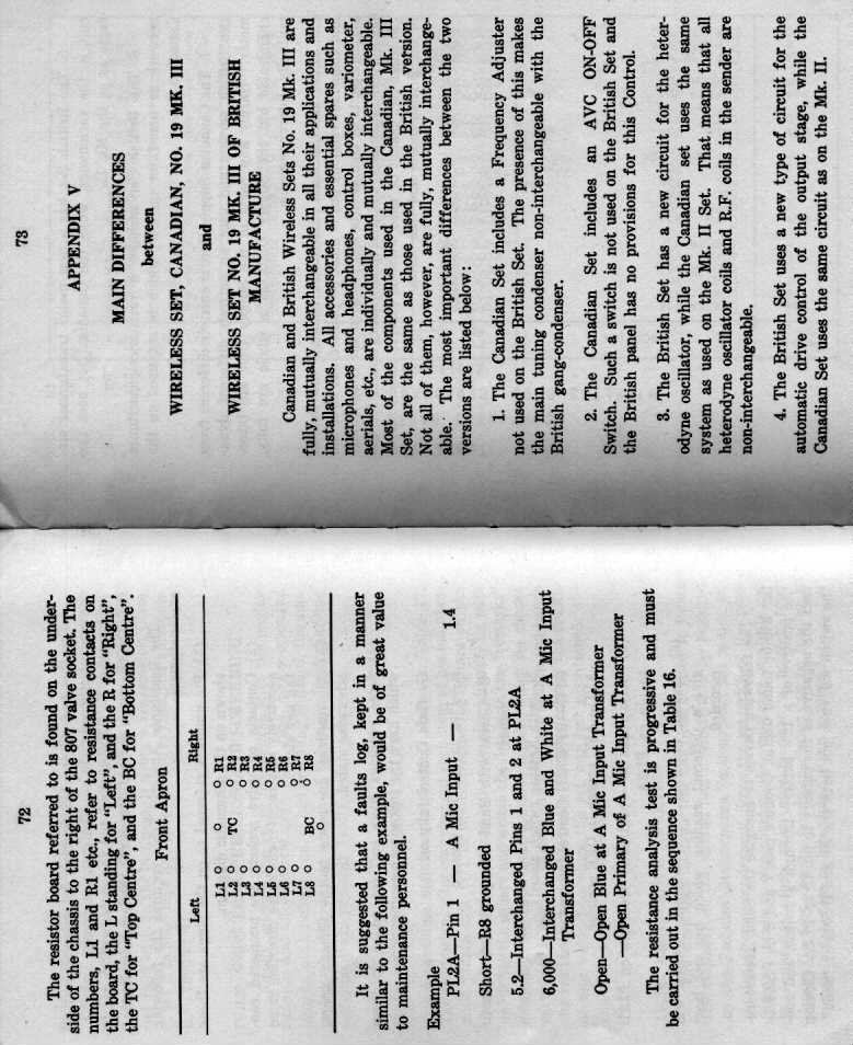
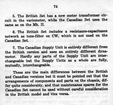
Appendix V: Main Differences between the WS#19 Canadian MK III and the WS#19 MK III of British manufacture, including frequency adjust, AVC, heterodyne oscillator, output stage, meter transformer circuit in variometer, CW tone filter, Supply Unit, etc.
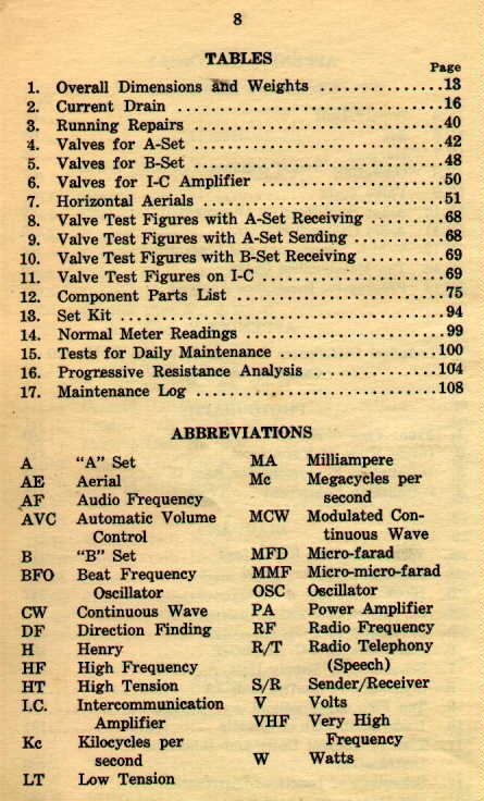
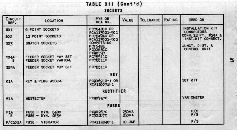
Table XII: Components parts list, including resistors, capacitors, sockets, key, rectifier, fuses, lamps, inductances, transformers, switches, plugs, jack, valves.
Table XIII: Set kit for WS#19 (Canadian) Mark III, a list of individual components in the set, needed to make it operate.
Table XIV: Normal meter readings.
Table XV: Tests for daily maintenance.
Table XVI: Progressive resistance analysis.
Table XVII: Sample maintenance log.
Photo 1: Front view of the WS#19 Mk III Canadian and the Supply Unit.
Photo 2: Inside view of the variometer.
RAM & Photo 3: Index to installation kit Cruiser Tank RAM I & II; Photo layout of installation equipment for RAM II.
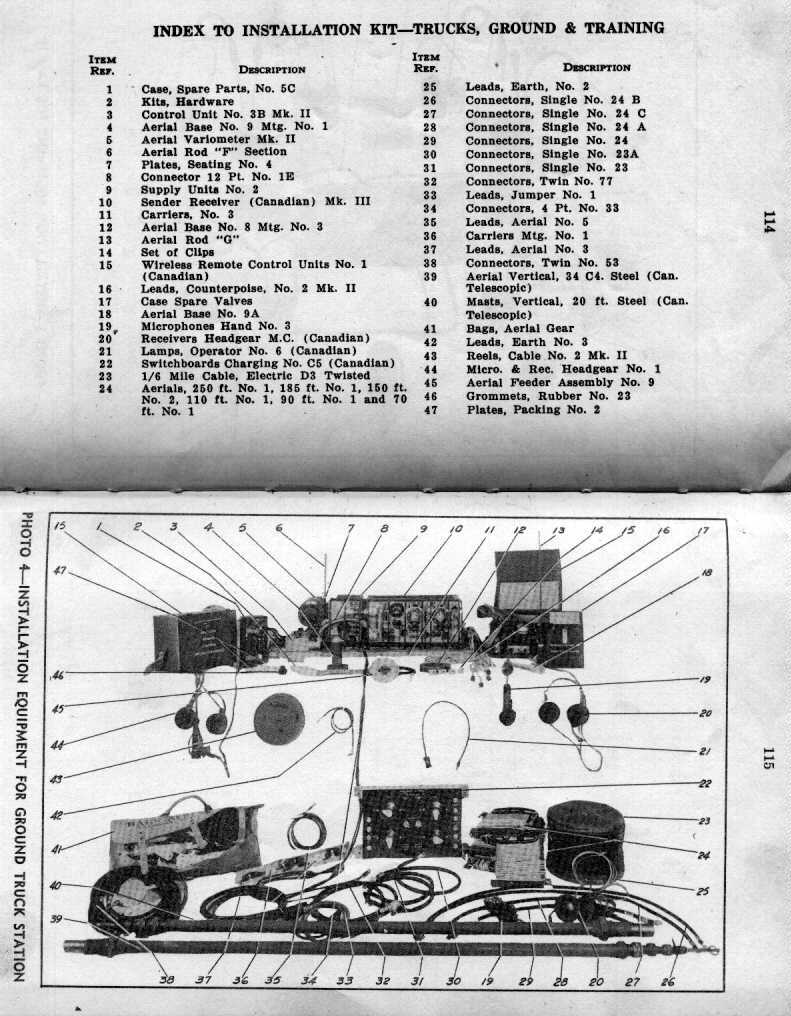
Install & Photo 4: Index to installation kit Trucks, Ground & Training; Photo layout of installation kit for Ground Truck Station.
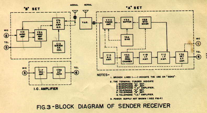
Figure 3: Block diagram of Sender/Receiver (both A and B set)..
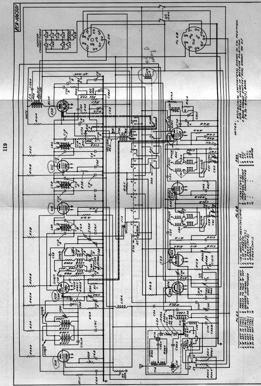
Figure 4: Schematic of "A" Set.
 Contents Page
5 Contents Page 6 Chap I, Page 9 Chap I, Pgs 10-11 Chap II, Pgs 12-13
Contents Page
5 Contents Page 6 Chap I, Page 9 Chap I, Pgs 10-11 Chap II, Pgs 12-13
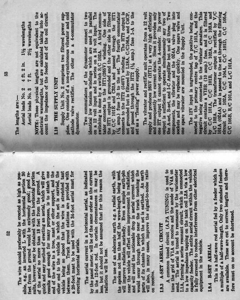
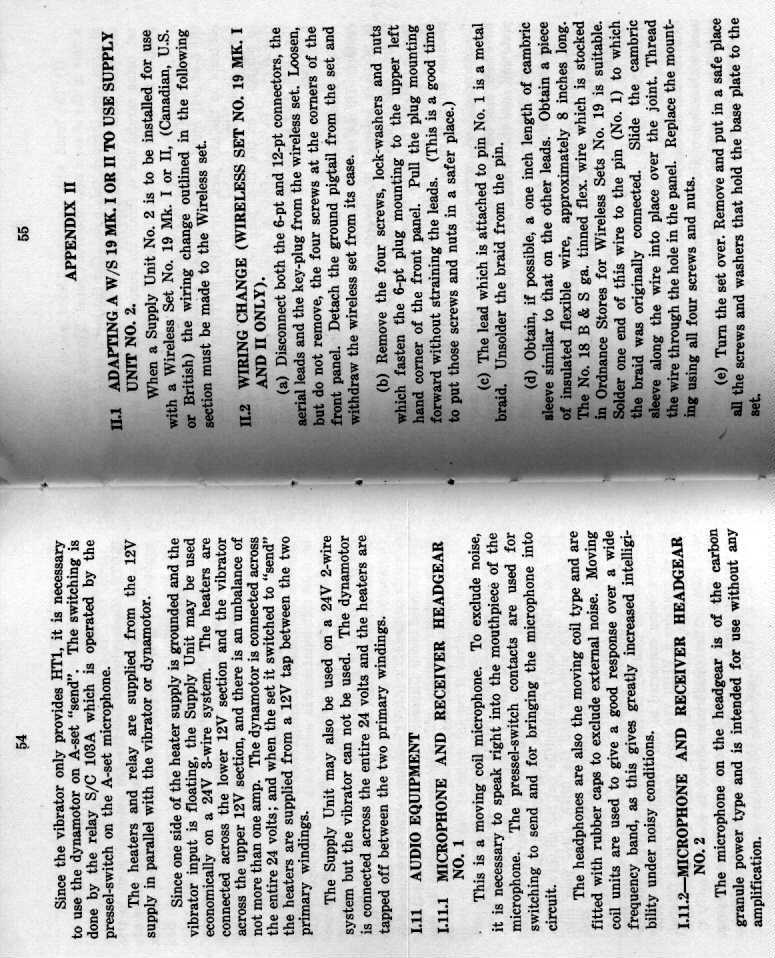
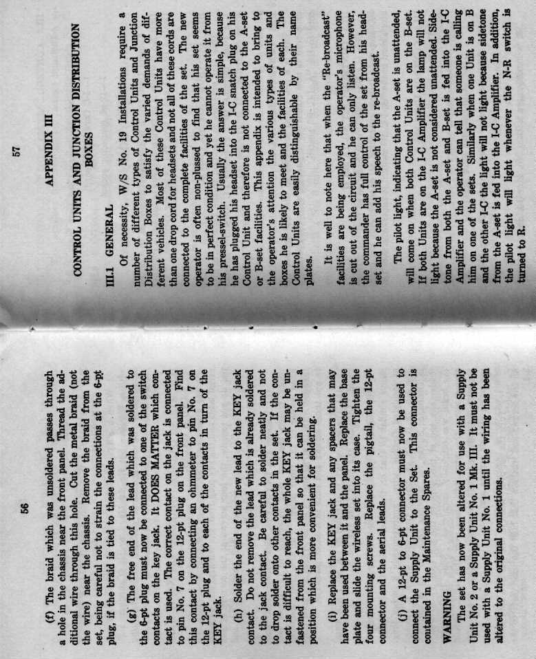
Append. I Pgs 52-53 Ap. I Pg 54 Ap. II Pg 55 Ap. II Pg 56 Ap. III Pg 57 Append. III Pgs 58-59 Append. III Pgs 60-61
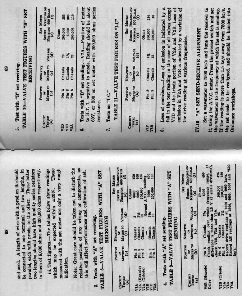
Append. III Pgs 62-63 Append. IV Pgs 64-65 Append. IV Pgs 66-67 Append. IV Pgs 68-69 Append. IV Pgs 70-71
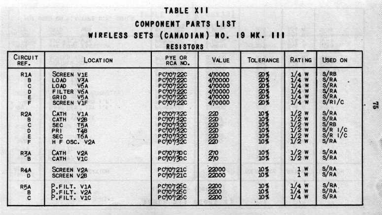
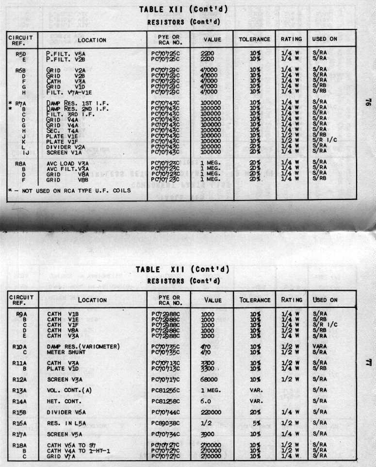
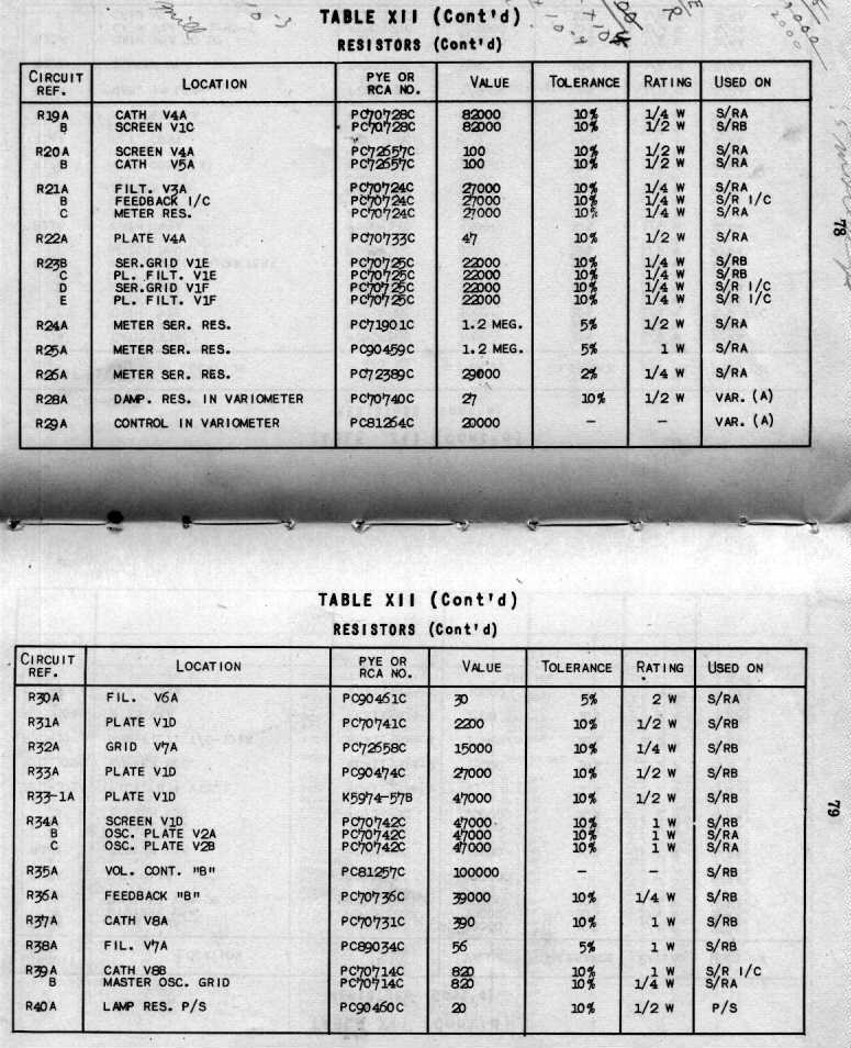
Ap. IV Pg 72 Ap. V Pg 73 Append. V Pg 74 Table XII Pg 75 Table XII Pgs 76-77 Table XII Pgs 78-79
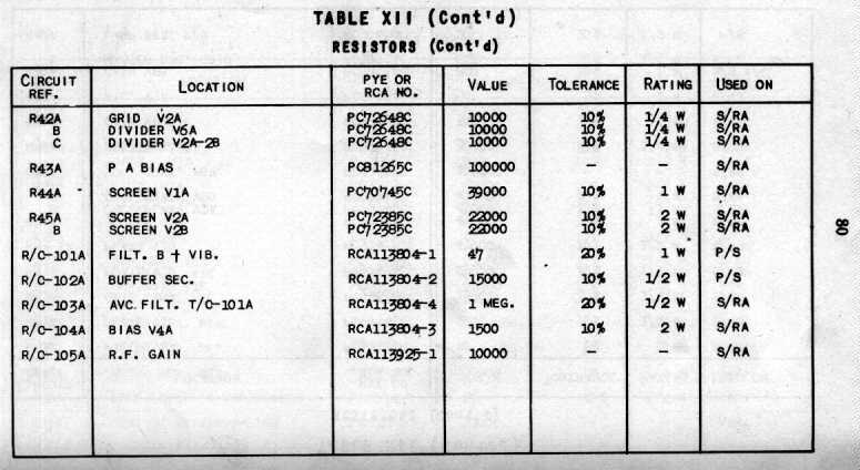
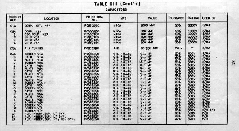
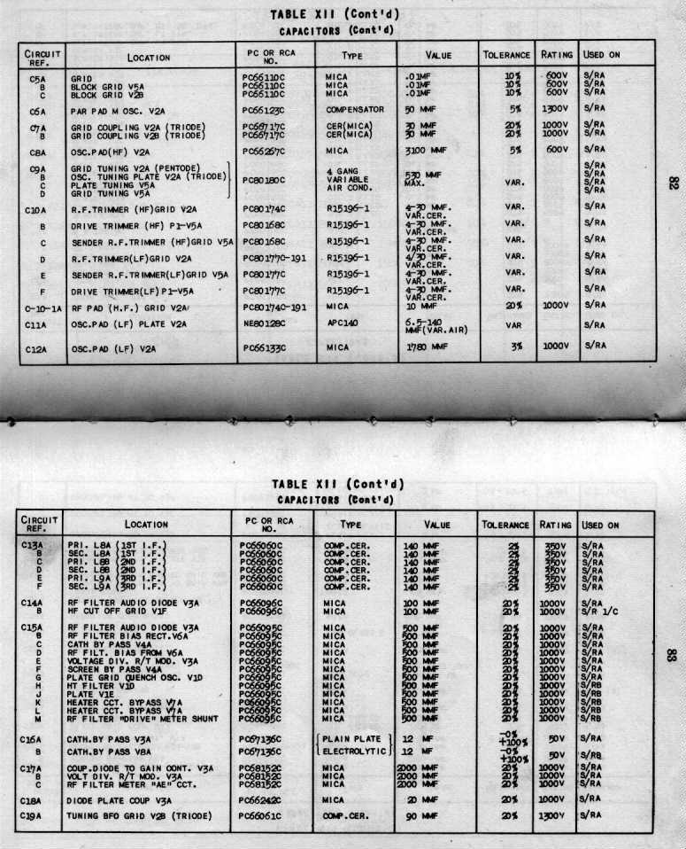
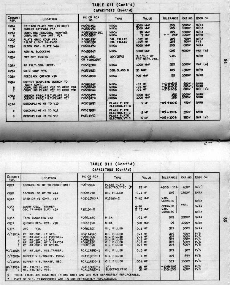
Table XII Pg 80 Table XII Pg 81 Table XII Pgs 82-83 Table XII Pgs 84-85
![]()
![]()
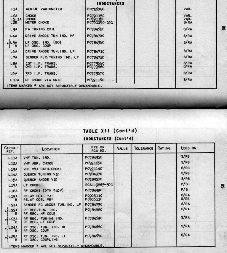
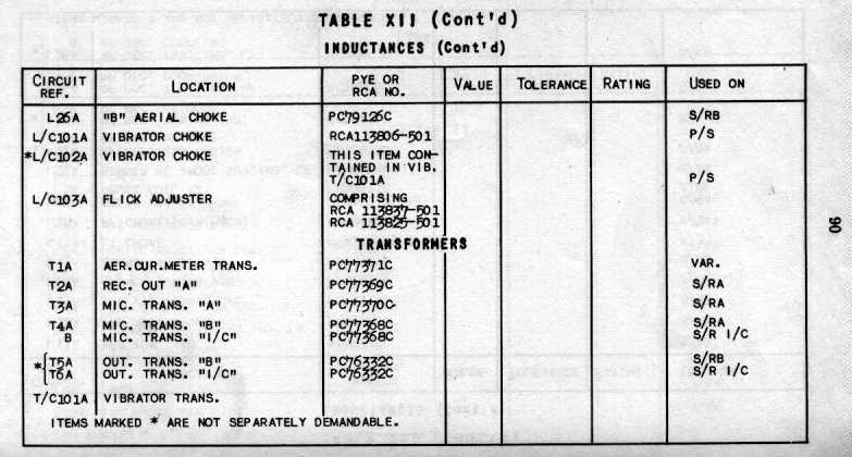
Table XII Pg 86 Table XII Pg 87 Table XII Pg 88 Lamps Table XII Pgs 88-89 Table XII Pg 90
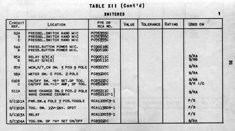
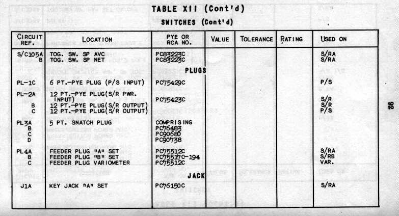
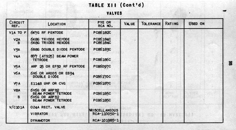
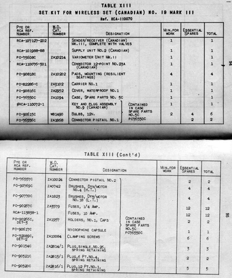
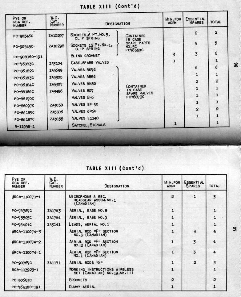
Table XII Pg 91 Table XII Pg 92 Table XII Pg 93 Table XIII Pgs 94-95 Table XIII Pgs 96-97
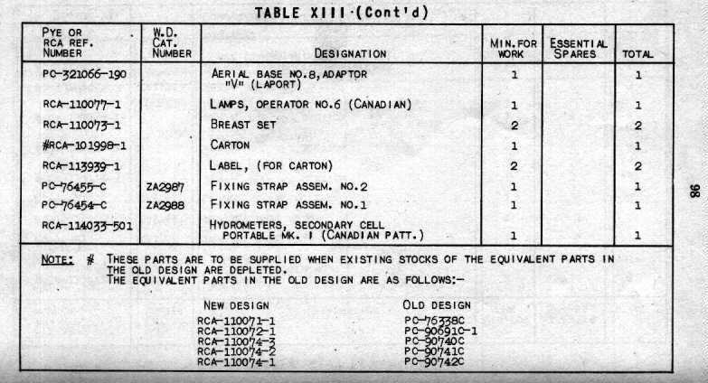
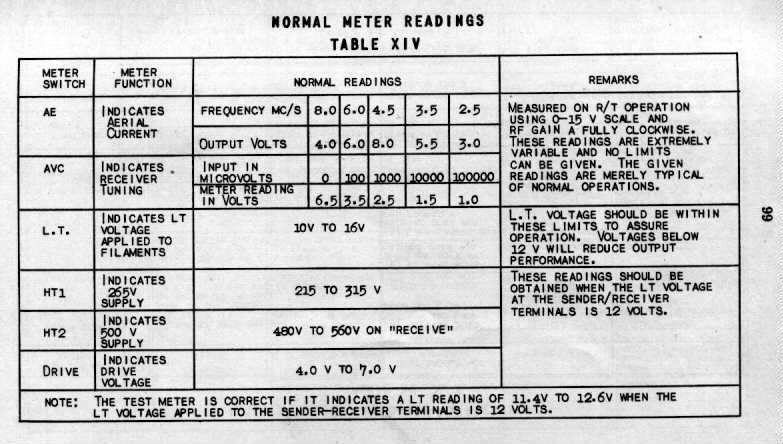
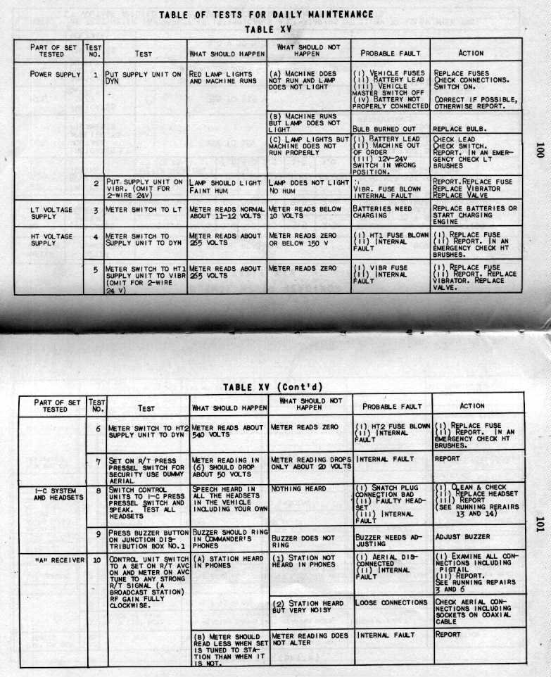
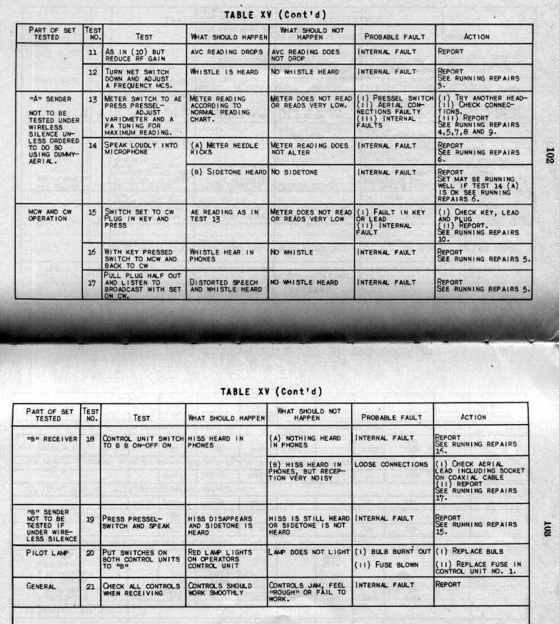
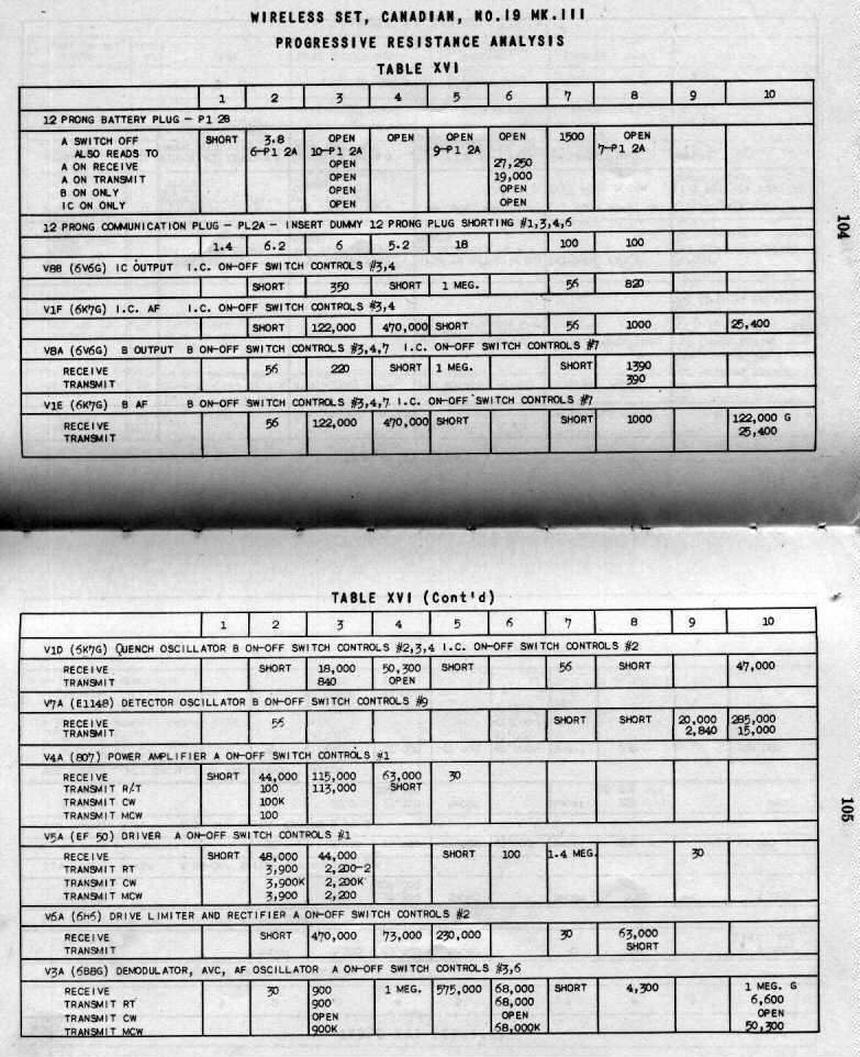
Table XIII Pg 98 Table XIV Pg 99 Table XV Pgs 100-01 Table XV Pgs 102-03 Table XVI Pgs 104-05
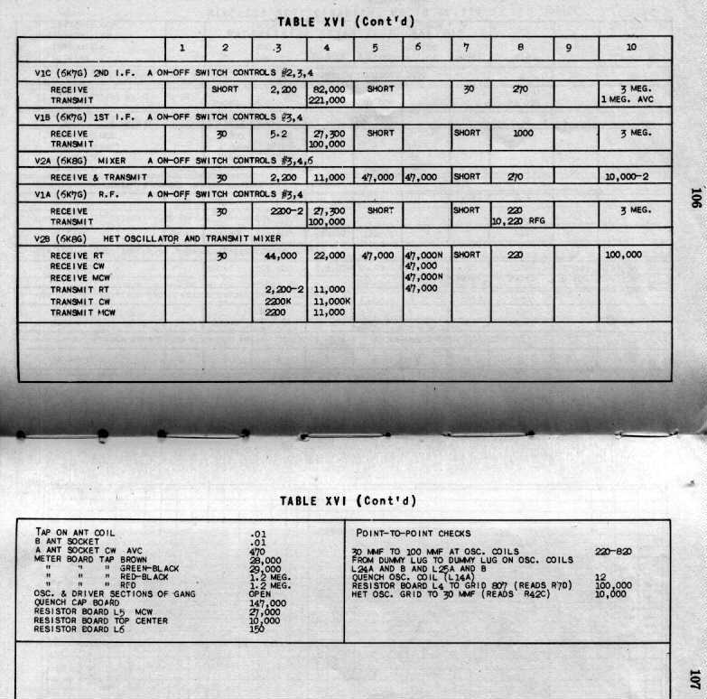
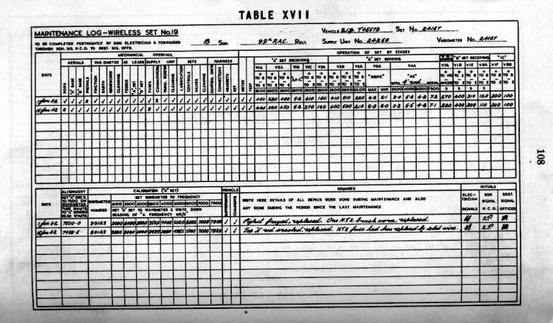
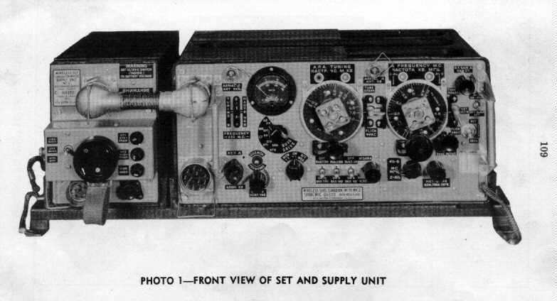
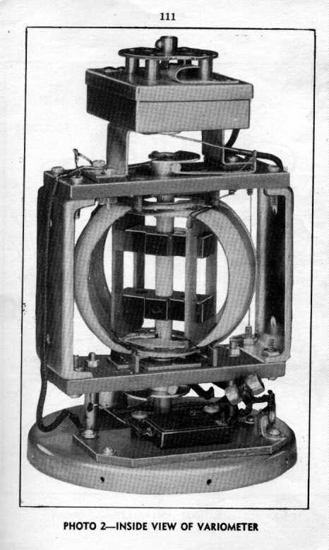
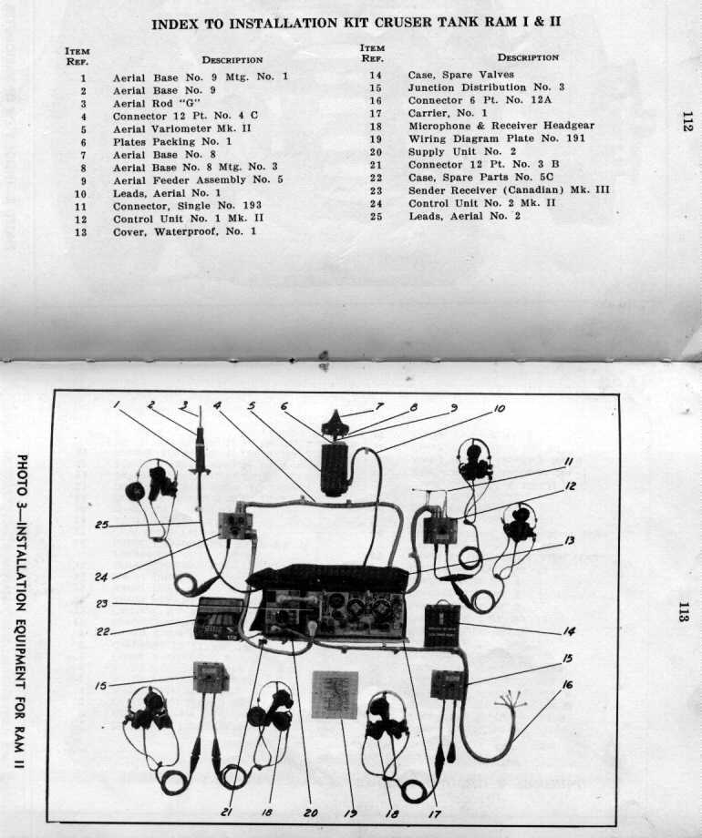
Table XVI Pgs 106-07 Table XVII Pg 108 Photo 1 Page 109 Photo 2 Page 111 RAM & Photo 3 Pgs 112-13
Install & Photo 4 Pgs 114-15 Fig. 3 Page 117 Fig. 4 Page 119
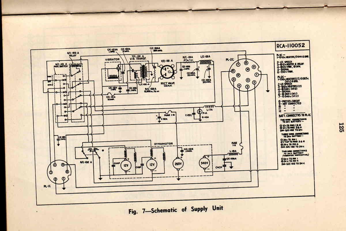
Fig. 7 Page 125
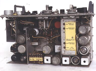
WS#19 MK III, CASE OFF, PHOTO BOTTOM VIEW
WS#19 MK III, CASE OFF, PHOTO TOP VIEW
Return to Wireless Set No. 19 Home Page
Copyright © R. D. (Bob) Cooke, VE3BDB (Orillia, Ontario, CANADA). All Rights Reserved