Wireless Set No. 19 Group
Sig/Telecom Section of MAMH
c/o 1309 Sunbury Rd, R.R. #2
Inverary, Ontario
CANADA K0H 1X0
2 January 2002
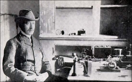
Guglielmo
Marconi, December 1901.
Marconi at Signal Hill with instruments used to receive the first Transatlantic
signals.
From
Marconi Company, Marconi Jubilee 1897-1947 (Chelmsford, England:
Marconi's Wireless Telegraph Company Limited, 1947) 18.
Final Report - Operation "Marconi 100"
INTRODUCTION
BACKGROUND.
1. Operation "MARCONI 100" was a special event in which members of the Wireless Set No. 19 Group used vintage equipment to mark the 100th anniversary of Guglielmo Marconi's trans-Atlantic wireless experiments of 1901. For this event, Group members used equipment which had been manufactured by the Marconi company to make contact with other amateur radio operators. An additional challenge was to have the cumulative distance of all of the contacts made by each operator, exceed the distance attempted by Marconi in 1901 (ie 3,421 Km).
2. Planning details for the event are outlined in the Operation Order (02 1726Z Dec '01). Phase I was a special edition of the regular Tuesday night training net. Its purpose was to give Group members an opportunity to make vintage-to-vintage contacts. Phase II was an independent activity in which members could make contact with any other amateur radio operator. For this phase VA3ORP operated portable from the Fort Henry Hill (Kingston, Ontario) which had been the site of station "VBH", a Marconi spark station established in 1914. The final part of the operation was a demonstration of a low-powered, rotary spark-gap transmitter that had been designed, constructed and operated by David Wilson (VE3BBN) of St David's, Ontario. Operation of this transmitter had been approved by Industry Canada for a one hour period during the evening of 12 Dec '01. This was limited to broadcasting the words "MARCONI S". Two-way communications using the spark transmitter were not attempted during this demonstration.
PURPOSE.
3. The purpose of this report is to document the events of Operation "MARCONI 100" and to capture any lessons learned.
DISCUSSION
OPERATIONS.
4. Participation. There were three 19 Set Group members for whom the cumulative distance of their QSOs exceeded the 3,421 Km attempted by Marconi (W1HIS with 8,210 Km using WS 19 MkIII; VA3ORP with 4,308 Km using WS 19 MkII and RCAF AT-1; VE3CBK with 4,048 Km using WS 19 MkIII). Three other operators participated by making at least one contact using Marconi manufactured equipment (W1NU with WS 19 MkII, VE3RIH with WS 19 MkIII and W1GDZ with WS 19 MkIII rx). In total there were 23 QSOs reported in which vintage Marconi equipment was used. Of particular note was W1HIS' WS 19 contact with EA6/SP4AOQ (Belmont, MA to Palma Nova, Mallorca) at a distance of 5,984 Km. The spark transmitter demonstration resulted in 58 reception reports which were considered valid. Greatest distance was 1,350 Km (St David's ON to Kansas City, KA).
5. QRM. While the interference level was not abnormal for the Phase I and II, the Spark demonstration suffered from QRM. There was another station with a "spark like" signal on 3.550 MHz. This was clearly not a true spark signal as it had a narrow bandwidth (possibly a SSB transmitter being modulated with an audio "growl"). This required monitoring stations to tune a few kHz above or below 3.550 MHz to find a clear spot where the VE3BBN transmission could be heard. Some careful adjustment of receiver's bandwidth and centre frequency, plus an knowledge of what to expect, was helpful. Between the fades and QRM there were many opportunities to hear the true spark signal and several excellent recordings were made. It was never determined whether the QRM was intentional and it seemed that some of it might have been caused by people trying to make a two-way contact with VE3BBN. This raises a difficult question about scheduling special events. With no advertising, it is more likely that a clear frequency can be maintained for a small group. If wider operator interest is created, the potential of QRM increases significantly (especially for something as special as a centenary event). In this case, an alternative might have been to get permission to transmit outside of the amateur bands, however this presents another set of equally difficult problems.
6. Net Control. Phase I was conducted as a normal directed net with the NCS using low-powered vintage equipment. After check-ins were taken, the NCS asked each station to send only his name, QTH, and equipment type. After all of these had been transmitted, each station was asked to give signal reports for all of the stations being heard. Finally, NCS asked if any station needed a repeat of any of the information. In this way, each station was able to log a contact from all of the other stations in the net, complete with individual signal reports, in a very short time. Although this procedure had not been discussed or practiced previously, its' implementation was simple and effective. Phase II was conducted as independent activity by each operator. The spark demonstration was a one-way broadcast without benefit of a Net Control Station.
TECHNICAL.
7. Propagation. Propagation for the period was satisfactory and seemed to support all planned skeds. Solar conditions for 12 Dec '01 were SF=222.6, A Index=12 (7-36), Kp=2225 3233, Kb=1235 3122. For 13 Dec '01 conditions were SF=220.2, A Index 4 (2-7), Kp=2110 2111, Kb=2121 0211. (Note: The link from VE3BBN's spark transmitter to Kansas City required one F layer refraction with a radiation angle of 24 degrees. Propagation analysis suggests that this should have been a reliable circuit at 0200Z on 12 Dec '01).
8. Equipment Preparation. This was particularly important for the deployment to the Fort Henry Hill (everything seems to be harder when working out of the trunk of a car, operating against a time limit and with spectators/reporters present). In checking the WS 19 Mk II prior to the event, it was found that there was a netting error of approximately 1 KHz. The cause of this has not yet been determined, however, knowing about it allowed the operator to compensate. The use of a portable, digital frequency counter was a great help in both getting on frequency and staying there. This operation again showed the value of prior, on-air testing for any event that is time critical.
9. Antenna - Kite Borne. Several interesting antennae configurations were prepared for this event. VA3ORP planned to use a kite borne, 3/4 wavelength end-fed antenna ( 1/2 wavelength plus 12 feet, tuned by the 19 Set variometer). The kite used was a Jalbert type J-7.5, four chamber parafoil kite (90 cm long X 70 cm wide). The antenna wire was 7 strands of tinned copper, each strand 0.0105" dia, with a woven, waxed-cloth covering and an overall length of 23.95 M (1/2 wavelength at 7.020 MHz plus 12 feet). The antenna wire was twisted around the lower end of the kite string. This antenna had been flown successfully in a moderate breeze. With light winds it tended to drift to about a 45 degree position, however as wind speed increased it tended to rise to greater than 75 degrees. Pull on the kite string was measured at 2 to 5 Kg. Unfortuantely, wind conditions at Fort Henry were calm during the set-up period, so the kite could not be deployed. In its place, an inverted vee was installed with its apex 4 M up in a tree. The ends of the inverted vee were 0.5 M above ground level and the length was adjusted with an antenna bridge to be resonant at 7.020 MHz. The antenna was fed through RG-58 coax, throught a 40 pF series capacitor and then to the variometer. The operating location was on the top of a hill with an unobstructed horizon and with limestone beneath a thin layer of topsoil. The inverted vee was a good alternative for field operations as it is easily deployed, easily tuned and gives predictable results.
10. Antenna - Heli-Kite. W1HIS experimented with an antenna lifted by a "Helikite", which is a combination of a helium-filled balloon and a kite. The balloon component provides lift in the absence of wind; and the kite is supposed to provide lift to oppose the tendency of a simple balloon to be dragged down by wind. In practice, the Helikite's balloon had too little lift for the combined weight of the kite, its tether, and the antenna wire. Ultimately, the kite was abandoned and three helium-filled balloons, each approximately spherical and two feet in diameter, were used to lift a Dacron tether and an antenna wire.
11. The antenna was 28 M of Litz wire comprising 25 insulated strands of 40-gauge copper wire, connected at the bottom to the WS 19 Variometer. It was planned to use this antenna to listen for the VE3BBN spark transmission at 3.550 MHz, and for both transmitting and receiving with a WS 19 on 3.7 and 7.0 MHz. Computer simulation predicted that the input impedance of this antenna, base-fed with respect to a 3.6 square-meter counterpoise, four metres above ground at 7 MHz would have a Real (resistive) part of 60 ohms and an Imaginary (reactive) part of -575 ohms; thus an excellent match to the WS 19 would be achieved. This antenna also promised to have more gain at low elevation angles than the regular W1HIS station antenna, a horizontal doublet 7 M above ground.
12. Unfortunately, so much time was spent dealing with the Helikite and the balloons, that the planned counterpoise was never deployed. With the substitute ground system, the feedpoint impedance was higher so less than full transmitted power could be coupled to the antenna. In addition, the balloon-lifted vertical antenna was found to be much noisier for receiving than the horizontal doublet with its well-balanced, common-mode-choked, feed. In the end, the horizontal doublet was used (successfully) both for listening at 3.550 MHz and for transceiving at 3.7 and 7 MHz.
13. Spark Transmitter. This transmitter was a conventional design based on reference material from the turn of the century. It had a 16 point (8 pair) rotary gap turning at 1800 RPM. Spectrum analysis showed a -3 dB bandwidth of 25 KHz, however the skirts of signal were very broad. A comparison test was done with a 5 Watt CW transmitter and it was found that the spark signal was 23 dB below the level of that 5 watt signal. Using a conventional, narrow bandwidth receiver this would be the equivalent of a 25 mW signal. It was assumed that such a signal, even with its wide bandwidth, would not cause any significant interference on the amateur bands. In receiving tests it was found that AM detection with 3 KHz bandwidth gave good results. With an experienced operator and a commercial grade communications receiver at a distance of 260 Km, the spark signal could be detected up to 50 KHz either side of the centre frequency of 3.550 MHz. In practice it was found that staying within 10 KHz gave much better results. During the demonstration, several recordings were made of the signal. It was found that random noise and fading caused at least as much degradation to the recordings as did man-made interference.
14. The transmitter evolved significantly throughout the design and testing phase. It was first built for 600 KHz hoping to triple in the final tank circuit to 1.800 MHz in the 160 M band. This provided tremendous power (about 400 W) but getting the final tank to stay on frequency without causing the reflected power back into the primary to actually reduce the output, caused a problem. The next step was to put the primary on 160 M along with the secondary. This proved very effective and the resulting power output was approx. 200 watts. Unfortunately, tests with W1HIS showed that transmitting that distance (648 Km) on 160 M with the antennae available was problematic, so this was abandoned for 80 M. Although the maximum power available on 80 meters was only about 50 watts the propagation was much better and, as many more hams use 80 than 160 M, the higher frequency was selected. In the final design, output coupling was reduced in the interest of creating the greatest power density in the narrowest possible bandwidth. The resulting output power was measured at 15 Watts, however, this was spread over a significant part of the spectrum.
15. After many frustrating weeks of independent testing (and getting only 10 miles with ground wave mode) an alternate testing method was selected. The ONTARS net was asked to send all available operators to 3.550 MHz to listen for the burst of noise. There were 45 reports on two successive occasions at distances of from 15 to 725 Km. One two-way contact was made in which the spark transmitter was used to communicate with a W.S. No. 19 Mk II at a distance of 261 Km. Once it had been confirmed that the spark transmitter actually worked, details of this phase of the operation were advertised throughout the amateur radio community.
ADMINISTRATION.
16. Orders. The Op Order was issued via email in draft (15 2000Z Oct '01) and final form (02 1726Z Dec '01). This remains the only practical method of distributing details of an operation.
17. Media Coverage. One of the lessons learned from Op "FESSENDEN" (23 Dec '00) was that considerable effort is required to generate media interest. In this area, Op "MARCONI 100" was a huge success. There were newspaper articles in Kingston, ON; St Catharines, ON and Belmont, MA. Details were also given in both ARRL and RAC bulletins. One interview was given by VE3BBN over Voice of America. Photographs and details of the spark transmitter operation were picked up by a number of websites. While some of this improvement in coverage is likely due to Marconi being better known than Fessenden, the individual efforts of Group members clearly made a difference. In Kingston, it was found that by issuing a fairly detailed (one page) "Press Release", the reporter tended to get most of the details correct. This was unusual, especially for an event that has technical dimensions. All three newspaper articles noted the controversy surrounding the success of Marconi's experiments. In all cases this issue was handled well and suggests that the Group members went to some lengths to ensure that the issue was properly understood.
18. Approval Process. Obtaining Industry Canada approval to operate the spark transmitter was a high priority. Without this formal approval, operation of the sparker would have been illegal and likely to bring the Group into conflict with regulatory authorities. Fortunately, Radio Amateurs of Canada has excellent liaison with Industry Canada. A phone call to RAC Headquarters put us in touch with Industry Canada's Amateur Radio Service Centre. A formal request was then submitted which resulted in a Radio Inspector from Burlington, ON making a visit to evaluate the spark transmitter. Based on his assessment, the on-air demonstration was approved for a one hour period. Note that this process was begun on 10 Sep '01 and final approval was granted on 26 Nov '01 (only 16 days before the event). This resulted in the Op Order not being finalized until 2 Dec '01 - only 10 days before the event. The lesson from this is that anything outside of normal amateur operations requires some lead time. It was most encouraging to see the support that was received from both Radio Amateurs of Canada and Industry Canada.
CONCLUDING MATERIAL
CONCLUSIONS.
19. The operation is considered a complete success. Considerable interest was generated for the Marconi centenary and the Group obtained a great deal of public exposure. The DX results obtained using vintage equipment was truly exceptional.
20. David Wilson, VE3BBN, is highly commended for his work in the research, design, construction and operation of the spark transmitter. His enthusiasm proved to be highly infectious.
RECOMMENDATIONS.
21. For any event where media coverage is desired, it is important to include preparation in the initial planning. It is suggested that future Op Orders include a "Media" sub-paragraph as part of the "Coordinating Instructions".
22. Prior on-air testing of equipment proved it value during this operation. It is suggested that, prior to any operation, the Tuesday and Thursday CW nets be used for verification of equipment serviceability and resolution of any procedural issues.
23. Special events remain a strong catalyst for members to get on-air with their vintage equipment. It is recommended that members make note of any significant historical events so that commemorative events can be undertaken.
D. Lawrence, VA3ORP D. Wilson, VE3BBN C. Counselman, WHIS
Net Control Stn, WS# 19 Gp Member, WS 19 Gp Member, WS 19 Gp