THE WS#19 MK II MANUAL
The Wireless Set #19 Mk II
(As Manufactured in Canada and the U.S.A.)
Working Instructions -- Published by the Director of Signals Design, Army Engineering Design Branch, Department of Munitions and Supply, Ottawa, Canada. Approved by the Chief of the General Staff, Department of National Defence, Ottawa. 1st August, 1942. See bottom of this page for link to tables, schematics, etc.
INTRODUCTION:
1. Although mechanically and electrically interchangeable in the major components, a number of modifications were considered essential and were incorporated both in Canada and the USA. Primarily, these modifications were introduced in order to accommodate Canadian and USA manufacturing processes.
2. From the viewpoint of the operator, there should be no difference between the British and the Canadian Set. In order to assist operators to master quickly the operation of the Set, and, therefore, to derive the maximum of performance in the field, the operating instructions have been recorded in somewhat greater detail than in the British pamphlet.
3. In order to assist maintenance personnel, a table has been added (Table XI), in which the major modifications in Canadian and American Sets has been recorded.
CHAPTER 1, GENERAL DESCRIPTION:
1.1 Purpose
Wireless Set No. 19 Mk II has been designed to be used in Armoured Fighting Vehicles (A.F.V.), in various Wireless Trucks and as a ground station.
The Set consists of an "A" Set (Sender-Receiver), a "B" Set (Sender-Receiver), an Intercommunication (I.C.) Amplifier and a Supply Unit.
Table I shows weight and overall dimensions of Set and Supply Unit; Table II shows the facilities, purposes and ranges of the complete No. 19 Set, Mk II.
TABLE I
TABLE I Weights and Dimensions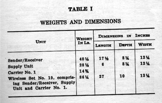
TABLE II
TABLE II Facilities Provided by a Complete Station No. 19, Mk II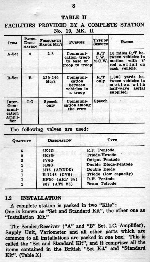
A Set: 2-8 Mc/s. Communication troop to base or troop to troop. R/T, CW, MCW. Range 10 miles R/T between vehicles in motion with 8' rod aerial on each vehicle.
B Set: 230-240 Mc/s. Communication between vehicles in a troop. R/T only. Range 1,000 yards between vehicles in motion with half-wave aerial supplied.
InterCommunicatiion Amplifier. Speech only. Communication among the crew.
The following valves (tubes) are used:
6 x 6K7G RF Pentode; 2 x 6K8G Triode-Hexode; 2 x 6V6G Output Pentode; 1 x 6B8G Double Diode-Pentode; 1 x 6H6 (ARDD5) Double Diode; 1 x E-1143 (CV6) Triode (low capacity); 1 x EF50 (ARP 35) RF Pentode; 1 x 807 (ATS 25) Beam Tetrode.
1.2 Installation
A complete station is packed in two "kits": One is known as "Set and Standard Kit:, the other one as "Installation Kit".
The Sender/Receiver ("A" and "B" Set, I.C. Amplifier), Supply Unit, Variometer and all other parts which are common to all installations are packed in one box. This is called the "Set and Standard Kit" and it comprises all of the items contained in the British "Set Kit" and "Standard Kit". (Table X)
For every type of vehicle in which the No. 19 Set is used, a second separate kit, called the "Installation Kit", is provided, which contains all the parts necessary for the installation in a particular vehicle.
1.3 The "A" Set Circuit (This para refers to schematics which I am not, at this point, able to reproduce. Anyone with a scanner, willing to do this for us?)
1.3.1 Frequency Range
The Set covers the frequency Range from 2 Mc/s (150M) to 8 Mc/s (37.5M) in two bands. One band covers from 2 Mc/s (150M) to 4 � Mc/s (66.6M) and the other from 4 � Mc/s (66.6M) to 8 Mc/s (37.5M). The desired band is selected by switch S11A (See Photo of 19 Set Front), which will be referred to as the Band-Change switch.
1.3.2 Aerials
The "A" Set is designed primarily for use with 8' or 12' rod aerials of the type supplied with the equipment. Where short range communication only is required, under conditions in which the 8' aerial would be regarded as too conspicuous, a single 4' section may be used.
Any of the usual types of elevated aerials can be used with the "A" Set, and the conditions governing the connection and tuning of the two most suitable types are set out in Table III.
TABLE III
Whip aerial. Three 4-Ft. sections (vertical). Mounted on Aerial Base No. 8; connected to Variometer, which is connected to AE socket on panel. Tuned for maximum reading of test meter by successive adjustments of Variometer and "P.A. Tuning".
Three-quarter wave end-fed aerial (horizontal). Erected at the greatest possible elevation; connected to Variometer which is connected to AE socket on panel. The use of a proper Earth will greatly improve radiation. Tuned as above. Length of wire to cover the appropriate frequency bands should be:
250' --- 2.0 - 2.65 Mc/s
185' --- 2.60 - 3.50 "
150' --- 3.45 - 4.50 "
110' --- 4.45 - 5.60 "
90' ---- 5.55 - 6.65 "
70' ---- 6.60 - 8.00 "
1.3.3 Receiver Circuit (Fig. 2)
The receiver is of the Superheterodyne type. The intermediate frequency (I.F.) is 465 Kc/s.
The receiver comprises the following stages:
=============================================
(1) - Signal Frequency --------------- 6K7G -- V1A
(2) - Oscillator, Freq. Changer ---- 6K8G -- V2A
(3) - I.F. Amplifier ------------------------ 6K7G -- V1B
(4) - I.F. Amplifier ------------------------ 6K7G -- V1C
(5) - Detector, AVC, Audio Amp.- 6B8G -- V3A
(6) - Heterodyne Oscillator(BF0)-- 6B8G -- V2B
=============================================
1.3.4 Sender Circuit (Fig. 2)
In order to eliminate separate adjustment of the sender, and to assure that always the same frequency is transmitted and received, the outputs of the receiver oscillator and the het. oscillator are mixed in Valve V2B to reconstitute a sender frequency equal to the frequency to which the receiver is tuned. This frequency is selected by the tuned buffer stage V5A (ARP 35 or EF50), and the output of this stage is applied to the grid of the Power Amplifier (P.A.)--stage V4A (807). Bias for the P.A. stage is obtained by rectification from the output of V5A in the diode V6A (ARDD 5 or 6H6), and the input voltage and bias are held constant by bias applied to the grid of V5A and obtained from the delayed diode rectifier V6A (ARDD 5 or 6H6). The output of the Power Amplifier is coupled to the aerial by means of a low impedance line Aerial Feeder No. 1, connected to a suitable tapping on the tank coil, L3A. The aerial is inductively loaded to resonance by means of the Aerial Tuning Variometer L1A, which is located in all cases as near as possible to the base of the aerial.
The Sender comprises the following stages:
==============================================================
(1) - Receiver Oscillator --------------- 6K8G ----------- V2A
(2) - Heterodyne Oscillator and Mixer --- 6K8G ----------- V2B
(3) - Buffer Stage ---------------------- ARP35 or EF50 -- V5A
(4) - Power Amplifier ------------------- 807 ------------ V4A
(5) - Modulator (on R/T), A.F. Oscillator
and Modulator (on M.C.W.) --------- 6B8G ----------- V3A
(6) - Grid Bias & Automatic Drive Cntrl - ARDD5 or 6H6 --- V6A
==============================================================
Table IV shows designation, type, function and circuit details of every valve.
1.3.5 Aerial Circuit (Fig. 3)
A tuned circuit consisting of L3A, C3A (labelled "P.A. Tuning" on the panel) is used to tune the grid of V1A, when receiving, and the anode of V4A when sending.
The aerial is tuned to resonance by the Variometer L1A and this series resonance circuit is connected to a tap on the Tank Coil L3A via a special feeder. The entire aerial circuit within the vehicle is fully screened to reduce interference from other electrical equipment within the vehicle.
The Variometer assembly includes a current transformer T1A and a rectifier unit W1A, enabling the R.F. current to be measured in the aerial lead at the point where it leaves the Variometer. The D.C. current from the rectifier is fed back to the set over the aerial feeder and measured by the meter on the panel, when the meter switch S8A is set to "AE". (See Fig. 3 and Photo 4).
From the Variometer the aerial lead is taken to Aerial Base No. 8 (the type of feeder etc., depends on the type of vehicle) into which one, two or three sections of the whip (Aerial, Type F) are inserted.
NOTE: The Variometer supplied with No. 19 Set Mk II is a Mk II version. It includes an adjustment permitting calibration of D.C. output of rectifier W1A and a filter circuit for D.C.. The Variometer is calibrated at the factory prior to shipment. It will retain its calibration in normal service and the adjusted rheostat should not be touched.
However, should it become necessary to recalibrate at any time, this may be done by setting up a station with a Variometer which operates satisfactorily and noting the Test Meter reading with switch to "AE" and set "in tune". The Variometer to be calibrated may then be inserted in place of the normal Variometer, tuned to give maximum output, and the meter adjustment rheostat (R29A) in Variometer rotated to give approximately the reading noted with previous Variometer. It will be as well to check the readings at low (say 2.5) and high (say 7.5) Mc/s. Refer to the tag enclosed with Variometer Mk. II.
1.4 The "B" Set Circuit (Fig. 2)
The "B" Set is a very high frequency (VHF) Sender-Receiver. It covers the frequency range from 230 Mc/s (1.3 M) to 240 Mc/s (1.2 M).
The Receiver comprises the following stages:
======================================================
STAGE-----------------------------------------------VALVE--------------DESIGNATION
1) R.F. ----------------------------------------------E 1148 or CV6------- V7A
2) Quench Frequency Oscillator ----------6K7G -------------------- V1D
3) Audio Amplifier -------------------------------6K7G -------------------- V1E
4) Audio Amplifier ------------------------------6V6G -------------------- V8A
======================================================
The Sender comprises the following stages:
1) Audio Amplifier -------------------------------6K7G --------------------V1E
2) Audio Amplifier & Modulator -----------6K7G --------------------V8E
3) Master Oscillator & Output -------------E 1148 or CV6-------V7A
The output of the "B" Set is fed through a special feeder from the terminal marked "Aerial B" straight to the Aerial Base No. 9. No special tuning of the aerial circuit is necessary as it is tuned when tuning the master oscillator by operation "Tuning B" � 25 A). (See photo 1).
1.5 The Intercommunication Amplifier (Fig. 2)
The I.C Amplifier provide communications for the crew within the vehicle. It is a two-stage amplifier comprising the following stages:
======================================================
STAGE ----------------------------------------------VALVE------------DESIGNATION
1) Pre-amplifier -------------------------------------- 6K7G ------------ V1F
2) A.F.Output ---------------------------------------- 6V6G -------------V8B
======================================================
1.6 The Supply Unit (Fig. 4)
Supply Unit No. 1 consists of a Rotary Transformer, associated filter circuits, input an output plug mounts (PL1C, PL1B), ON-OFF switch (S 6 A), pilot lamp (P 1 A), fuses (F 1 A, F 1 B), etc.
The Rotary Transformer is a three commutator machine, operating from a nominal L.T. input of 12 volts. It provides two high voltage D.C. outputs, one of 275 volts and the other of 500 volts. These outputs are smoothed by filter circuits (L18A, L18B, C4CP, C32A, C33A). The L.T. input circuit to the Rotary Transformer is floating (i.e. ungrounded). It is opened and closed by a section of the OFF-ON Switch S 6 A.
The Low Tension (12 volts) circuit for the valve heaters, pilot lamps and relay operation is carried from the input plug mount (PL 1 C) to the output plug mount (PL 1 B) through section of switch S 6 A. One side of this circuit (the negative) is grounded to the case of the Power Supply Unit.
Since the L.T. Rotary Transformer circuit is floating, it may be operated across one 12 volt section of a 24 volt battery while the L.T. valve heater circuit is operated across the other section of the battery (ground section).
Since the current drain of the L.T. Rotary Transformer, when sending on "A" Set, is higher than that of the valve heater circuit, it is essential that the 12 volt tap from a 24 volt battery be brought out and connected to the junction of positive L.T. heater and negative L.T. Rotary Transformer.
It is important that this 12 volt tap on 24 volt battery be in position while the wireless set is operating. Should it go open with the "A" Set sending, the valve heaters will be permanently damaged. For this reason no fuse should be used in this 12 volt tap.
1.7 Current Drain
With a battery voltage of 12 volts, the current drain of the No. 19 set is:
for "A" Receiver only ----------------------------------------------------approx. 6.5 A
for "A" Sender on R/T ---------------------------------------------------approx. 7.5 A
for "A" Sender on C.W. -------------------------------------------------approx. 9.0 A
for "A" Receiver, "B" Receiver, I.C. Amplifier----------------------------approx. 8.0 A
1.8 Control Units and Junction Distribution Boxes
The control units and junction boxes are installed within easy reach of every man who has to make use of the facilities provided by the No. 19 Set.
Junction distribution boxes are connected to the Intercommunications system only. Junction distribution No. 1 and 3 have a special buzzer operated by a push-button. The signal produced by this buzzer can be heard in the Commander's earphones and serves as an emergency signal.
The type and number of control units depends on the vehicle in which the station is installed. The installation instructions supplied with every installation kit and vehicle contain detailed descriptions on how to install the whole station.
The control unit is connected to the set by a special connector. This connector carries all the leads for microphone, receiver, pressel-switch, etc. The unit itself has one or several drop-leads, with snatch-plugs for Microphone and Receiver Headgear. By means of a selector switch on the control unit the required facility may be selected. This arrangement enables the separate, independent use of every facility provided by the No. 19 Set.
Very soon, all existing control units will be replaced by Control Units Mark II. The special feature of this unit is the "Re-Broadcast" or "Re-Transmit" facility. It has, in addition to the selector switch, a second two-position switch. The positions are marked "N" and "R". In the "N" position a Mark II unit works like a Mark I unit and provides the normal facilities.
In the "R" position � for Re-Broadcast), the following additional possibilities are made available:
(1) "Receive on "B" and "Send" on "A" Set (Output of "B" modulates the "A" Sender).
(2) "Send" or "Receive" on "A" and "B" simultaneously.
(3) "Receive" on "A" and "Send" on "B" Set. (Output of "A" modulates the "B" Sender).
(See Switching charts on Tables VI and VII for operation and facilities in two particular installations.)
A vehicle equipped with a Mark II Control Unit can act as Relay Station, and, at the same time, enable the Commander of this vehicle to add his own speech to the re-broadcast.
1.9 The Controls
The details, functions and operation of all the controls are shown in Table V. The positions may be seen in Photo 1 and Fig. 7.
CHAPTER II, OPERATING INSTRUCTIONS (Photo 1; Fig. 1-7; Table V)
2.1 Preliminary
A. Roll up the waterproof cover and secure it on top of the set.
B. See that set, variometer, aerials, batteries, control units, headgear, etc. are properly connected according to the installation instructions supplied with every vehicle.
C. Put "OFF-ON B" (S9A) to "OFF". (If it is at "ON", there is risk of blowing valve V7A).
D. Switch on power-supply "ON-OFF" switch (S6A) on panel of Supply Unit.
E. Check H.T. and L.T. voltages by means of the Test Meter, operating the meter switch (S8A) (Table VIII gives the limits within which the meter readings should be). The valve heaters take about thirty seconds to warm up, and this interval should be permitted before sender or receiver are operated.
F. Switch "OFF-ON B" (S9A) to "ON B" and make sure that "A ONLY-ALL" (S10A) is on "ALL".
G. When the valves have warmed up, check that intercommunication between all members of the crew is satisfactory with the Control Units set to "I.C.". Note that when both switches are set to "B", the warning lamp on the Control Lamp will light up, indicating that A-Set is unattended.
H. Turn switch on Control Unit to "A". Turn "Gain A" (R13A) fully clockwise. Set dials of "Frequency Mc/s" (Ganged condensers C9A, B, C and D) and "P.A. Tuning" (C3A) to the same frequency. Rotate Variometer, and the signal or noise strength will indicate that receiver and aerial circuits are working properly.
(Note: NO paragraph 'I'.)
J. Press Pressel-Switch on microphone, turn meter switch (S8A) to "AE" and note that a reading is obtained, showing that the sender is operating. (See 2.2.2. for tuning procedure).
K. Turn switch on Control Unit to "B". Turn "GAIN B" clockwise as required. A rushing (quench noise) indicates that the "B" set receiver is operating. This noise will disappear when the pressel-switch is pressed, indicating that the "B" set has been switched to "SEND".
WARNING: Utmost care should be taken when pressing the pressel-switch either on the "A" or the "B" set, as this puts the transmitter "on the air" and enables the enemy to obtain a D.F. bearing.
2.2 Tuning of "A" Set
Under normal circumstances, several stations will work in a "GROUP" or "NET". Such a group consists of a number of sets tuned to the same frequency. One station, usually the set of the highest formation, is called the "Control-Station", the others are "Out-Stations". It is of utmost importance that all sets belonging to the same group are accurately tuned to the same frequency: the frequency of the control station.
Normally, a group will be give two frequencies to work on, the "blue" or normal and the "red" or spare frequency. The "Flick" mechanism permits tuning the set for working on either frequency, and to change quickly from one to the other.
By tuning and netting the receiver to the control station, the sender is automatically tuned to the same frequency.
To tune sender or receiver, proceed as follows:
2.2.1 Tuning and Netting of Receiver
A. Turn "Flick" controls to "Tune"
B. Set Band-change Switch (S11A) to the required frequency band.
C. Set both tuning dials to the frequency of the control station.
D. Rotate aerial variometer (T1A) until maximum signal strength or noise is heard in headgear. This is a check that the aerial circuits are approximately in tune. If Transmission Selector Switch (S7A) is set to R/T and control station is strong, a sharp dip in reading of Meter (Switch S8A set to A.V.C.) will indicate that the set is tuned correctly.
E. Re-adjust "Frequency Mc" and "P.A. Tuning" dials until control station is heard clearly.
F. Press "NET" button and adjust "Frequency Mc" dial until the beat note frequency is zero. When netting on "M.C.W." or while the other station is talking, the beat note will disappear, but the modulation can still be heard.
G. For C.W. reception, turn switch S7A to "C.W." and adjust beat note as desired by means of "HET TONE" control (R14A).
2.2.2 Tuning of Sender
A. Turn the Transmission Selector Switch (S7A) to the required position. (R/T, C.W., or M.C.W.)
B. Set Test Meter Switch (S8A) to "A.E.".
C. R/T: When working on R/T, press the pressel-switch of the microphone and adjust Variometer and "P.A. Tuning" knob until meter indicates maximum output. It is necessary to re-adjust both controls successively several times before maximum meter reading is obtained. Log Variometer setting.
D. C.W.: When working on C.W. or M.C.W., put plug assembly of morse key into the "KEY" jack on the set panel. If no suitable platform is found on which to rest the key, it must be strapped to the thigh.
When sending it is necessary for the plug to be pushed right home. The procedure to tune for maximum output is the same as for R/T. When working on C.W., however, it is necessary to press the key when tuning for maximum output. (If the key is not pressed, no aerial current will flow.) When receiving, the plug should be partially withdrawn. (If the key remains pushed in, the set stays on "Send" and no reception is possible.) Pushing the plug in, switches the Set to "Send" again. If the output circuits have been tuned for maximum output on R/T and the set is switched to C.W., and vice versa, it is necessary to retune them slightly, following the same procedure as before.
The Variometer needs re-adjusting whenever the frequency of the set or the length of the aerial is altered. When setting up for "Flick" working, note the variometer settings for the two frequencies on the writing tablet at the right-hand end of the set, and in the log, so that the variometer can be re-set quickly when changing frequency. There are two scales on the variometer: 0-100 and 200-100. The lower frequencies will have a setting on the lower scale (0-100), the lowest frequency near 10; high frequencies will have a setting on the higher scale (200-100), the highest near 110.
WARNING. The positions, where the change from one scale to another takes place, are marked by red bands. Never use a setting covered by either of these bands. If the setting is on or a little below either red band, say between 80 and 100 or between 180 and 200, always attempt to get better results at the top of the other range.
2.2.3 The "Flick" Dials (Fig. 7a)
The "Flick" mechanisms fitted to the two main dials ("Frequency Mc" and "P.A. Tuning") enable the adjustments of these controls to be pre-set for two frequencies. An almost instantaneous change from one frequency to another is thus made possible.
Adjacent to each main tuning dial is an auxiliary control marked "FLICK", "SET", AND "TUNE". In the "FLICK" position, two pre-determined tuning settings are indicated by spring-loaded followers, which drop into notches in two discs mounted on the condenser shaft. The coloured indicators above the dials indicate which of the two discs is engaged.
In the "FLICK" position, the slow motion drive is disengaged. With the "Flick" controls set to "TUNE", the "Flick" mechanism is disengaged and the slow motion drive functions in the normal manner.
To operate the "FLICK DIALS" proceed as follows:
1. Set Band-change Switch (S11A) to desired Band.
2. Engage either the blue or the red disc of each dial.
3. Turn the auxiliary controls to "Set".
4. Slacken off the appropriate (blue or red) locking screws on the front of the dial knobs.
5. Tune the receiver, by operating both dials, to the control station (paragraph 2.2.1).
6. Tighten locking screws of "Frequency Mcs" dial only.
7. Press the pressel-switch and rotate the Variometer dial for maximum aerial current. Log Variometer setting.
8. Re-adjust the "P.A. Tuning" dial for maximum aerial current and tighten locking screws.
9. Engage the other disc of each dial and repeat the entire process for the other frequency.
It is possible to fix both "flick" positions on the same band or have them on different bands. When setting the "Frequency Mc/s" control, care should be taken to read the correct dial. (According to the setting of the Band-change Switch.)
When changing from one "flick" position to another, the following procedure should be adopted:
1. Turn over "Frequency Mc" Control.
2. Turn over "P.A. Tuning" Control.
3. Change the Band-change Switch, when the new "flick" position is on another band.
4. Rotate the Variometer until maximum output is indicated by the test meter. This setting will be greatly facilitated if the Variometer position has been logged previously.
WARNING: When netting, do not tighten any locking screws, before all controls are adjusted for zero beat on Receive and maximum aerial current on Send.
NOTE: After having netted and tuned, the meter switch (S8A) should be left in the "AE" position. The meter will then always show a reading when the set is switched to Send, thus giving the operator an opportunity to check the operation.
2.3 Tuning and Netting the "B" Set
(1) Put the "A ONLY-ALL" switch to "ALL" (if it is not already there).
(2) Put the 'OFF-ON B" switch to "ON" (if not already done).
(3) Turn the switch on the control unit to "B".
(4) Turn the knob "GAIN B" to the right as far as it will go.
(5) Put the "B TUNING" disc to the ordered setting.
NETTING:
(6) Control Station presses his pressel-switch and calls the group.
(7) During this call, out-stations adjust their "B TUNING" discs till they hear control, turn the knob "GAIN B" down till control can only just be heard, and adjust the tuning discs for the clearest possible signal. They may then turn "GAIN B" up, if necessary, to hear control comfortably.
(8) Outstations answer in turn. During each answer, control tunes his "B" set to the outstation's signal as in (7), and notes the setting of his tuning disc. If this is more than one division different from the ordered frequency, the out-station is badly off net.
(9) Control station calls all out-stations one by one and tells them "O.K. off", if they have netted properly. If a station is badly off the net, he tells him to alter the setting of his tuning discs up or down, according to the notes made in (8) and to answer him again.
The "QUENCH" Adjuster. This should NEVER be touched except on orders from CONTROL.
(10 Sometimes a whistle interferes with the working of the group. If this happens, Control orders all outstations to screw their quench adjusters right IN, and does so himself. He then orders all outstations but one to switch their "B" sets off; call this one station "No. 1". If there is still a whistle, Control orders No. 1 to screw his adjuster slowly out again and both listen. When the whistle pitch is too high to be heard, No. 1 stops screwing, and tells Control "O.K".
(11) Control tells another outstation (call him "No. 2"), by shouting or other means, to switch his "B" set on. If there is a whistle, No. 2 screws his adjuster slowly out. When he can no longer hear the whistle, he stops screwing and tells Control "O.K.".
(12) The same drill is done again for the rest of the outstations. It should never be necessary to touch the "QUENCH" adjusters again until a new set joins the group.
2.4 Control and Intercommunication System
The installation of the Control and Intercommunication System depends on the type of vehicle in use. The installation instructions and circuit diagrams are supplied with every Installation Kit and Vehicle.
To operate the intercommunication system, it is only necessary to turn the switch on the control unit to I-C, and to press the pressel-switch when talking. Make sure that S10A is on position "ALL".
Tables VI and VII show the facilities provides by installations in a Canadian Infantry Tank Mk. III *** and a U.S. medium Tank M4. Figs. 8 and 9 show the wiring layout of these installations.
In the Infantry Tank, the Gunner's and Commander's headgears are connected to Control Unit No. 3 (Mk.I or Mk.II), and by means of a switch they select the facility they require. The Mark I unit has 2 switches only, S1C and S1D, by which the type of service is selected.
Control Unit No. 3, Mk.II has 3 switches, S1F, S13A and S14A. With S14A in position "N" (Normal), the facilities and operations are the same as on a Mk.I Unit.
With S14A in position "R" (Re-broadcast), the facilities as outlined on Table VI are available. The operation of the control and intercommunication system in a U.S. Medium Tank M4 is very similar. Fig. 9 and Table VII show all the details.
WARNING: WHEN SWITCH S14A IS IN "R" POSITION, SWITCH "OFF-ON B" (S9A) MUST BE IN "ON" POSITION, AND SWITCH "A ONLY-ALL" (S10A) MUST BE IN "ALL" POSITION.
2.5 Checking for Correction Operation
The following points should be checked with installing the set or after it has been out of operation for a long period:
1) Check that the operating voltages are correct, using the test meter on the set panel. (See Table VIII for limits.)
2) Check that the I-C Amplifier works satisfactorily. (Switches on Control Units to I-C.)
3) Check that the side-tone of "A" and "B" Sets can be heard when sending. (Switches on Control Units to "A" and "B" respectively.)
4) Check that the incoming signals on "A" and "B" Sets can be heard with the Control Unit switches set to "IC".
5) Check that the lamp on Control Unit lights, when the "A" Set is unattended. (Switches on Control Units to "B".)
6) Check that the aerial current and drive voltage are correct, using the test meter on
WARNING: Testing the side-tone of the "A" or "B" Set in the field should be omitted, as this gives the enemy a chance to obtain a D.F. bearing on the vehicle.
WS19 MkII Figures, Tables and Schematics
Return to Wireless Set No. 19 Home Page
Copyright � R. D. (Bob) Cooke, VE3BDB (Orillia, Ontario, CANADA). All Rights Reserved
COMING NEXT: The Mk III Manual, complete with tables!
Until then, here are two photos of the Mk III with case off:
WS#19 MK III, CASE OFF, BOTTOM VIEW
WS#19 MK III, CASE OFF, TOP VIEW