
High Level Modulation for the Wireless Set No. 19 using the Control Unit No. 10 (ZA 10454)
By: Chris Bisaillion VE3CBK, Whiskeytown Wireless Collection
Introduction:
I
have used a special high level modulation box called a Control Unit No. 10 (C.U.
No. 10) with my Wireless Set No. 19 on AM (R/T mode).
A number of out-stations have asked to learn more about this elusive
accessory for the No. 19.
The C.U. No. 10 has significantly contributed to my success in using the No. 19 in AM mode.
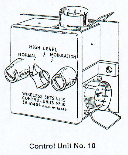
Figure
1 shows a line drawing for the C.U. No. 10.
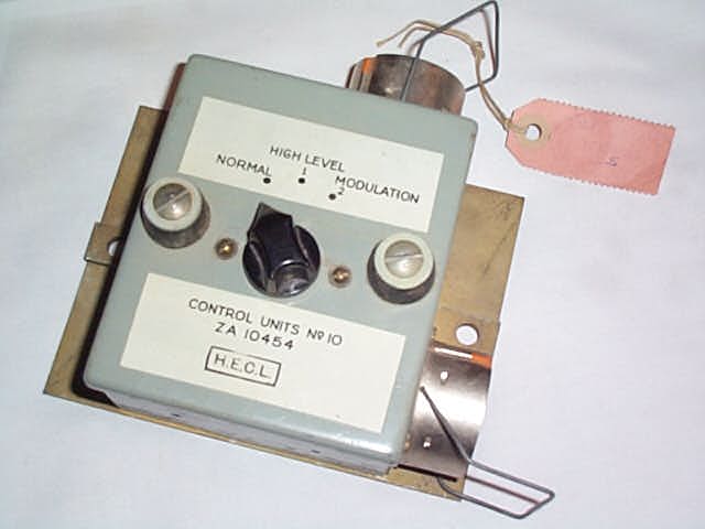
Figure 2
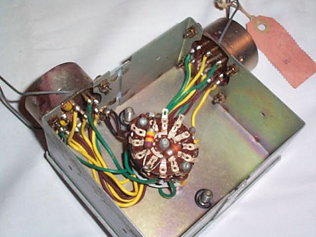
shows the outside view of the C.U. No. 10. Figure
3 shows the inside view of the C.U. No. 10.
The
original use for the C.U. No. 10 is described in the following two paragraphs:
From
‘Notes for RAC Wireless Instructors” dated 1947 (Reference No. 1):
Control
Unit No. 10
1. Two 12-point connector
sockets (output and input).
2. Switch
"Normal" -- "Mod 1" -- "Mod 2" giving two high
levels of modulation.
3. No Drop Leads.
This
Unit is for use in Command Vehicles to obviate the need for shouting. It is connected between the set and control unit, or between
any two control units and enables the "IC" to be used to amplify the
speech between the microphone and the "A Set" of the WS No. 19 when
the "IC" is not needed in the vehicle (i.e. when stationary).
From
EMER K402/3 (later known as L592) Issue 1, 31 Oct 1944 (Reference No. 2):
Control
Unit No. 10
12.
One or two of these units are provided in some installations connected to
the 19 set or sets. The unit has
one switch with three positions -- NORMAL and two degrees of HIGH LEVEL.
13.
The first position must always be used on the move and gives the normal
facilities of the 19 set. The other
positions are intended for use at the halt, to enable speakers to work the A set
without having to speak in the usual loud voice.
This is done by using the I.C. amplifier to amplify quiet speech in the A
set microphone, making it loud before feeding it into the A set itself.
Thus in these positions the I.C. of the set concerned must be switched on
but cannot be used normally.
14.
When using HIGH LEVEL MODULATION, one should not speak too loudly, or the
speech will be distorted in transmission.
For this
reason, it should not be used on the move.
When wireless conditions are bad and the speaker can only be just heard,
it is better to switch to NORMAL and speak loudly and clearly -- the HIGH LEVEL
MODULATION is designed to save the speaker's voice and does not give quite so
much range as NORMAL.
From
Wireless for the Warrior, Volume 2 (Reference No. 8):
Louis
Meulstee described the C.U. No. 10 in his book Wireless for the Warrior Vol 2.
The following is presented with his kind permission.
“Also
known as the 'high-mod' box or 'quiet' box, Control Unit No.10 is a special unit
with 12-pt input and output connectors. It has a three-position switch
labelled, NORMAL and two degrees of HIGH LEVEL modulation. The NORMAL
position must always be used when on the move and gives normal facilities of the
No. 19 Set. The other positions are intended to be used on a halt to
enable the speaker to work the A set without having to speak in the normal loud
voice.
The
unit is connected between the set and control units, or between ant two control
units and uses the IC amplifier to amplify the speech before it goes into the A
set. In the HIGH LEVEL positions, the IC of the set, though switched on,
cannot be used normally. When using high level modulation it is not
desireable to speak too loudly into the microphone or over-modulation will
occur. No drop leads are fitted on the No. 10 Control Unit.
It
was primarily used with Wiring Harness C in Armoured Command Vehicles and Lorry
Command Vehicles and various other command vehicles.”
Author's
notes:
The
C.U. No. 10 is unidirectional. If
you swap 12 point cable connections around, high level modulation will not work.
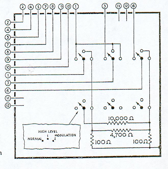
See
Figure 4 for a
schematic for the C.U. No. 10.
From
EMER FZ 254/3 (Reference No. 6), The Sensitivity Test for the IC Amplifier, the
minimum gain of the IC Amplifier has been calculated to be about 48 dB.
When
the C.U. No. 10 is in the "NORMAL" mode the "IC" works
normally and the microphone is connected to the A Set directly.
When
the C.U. No. 10 is in the "Mod 1" mode the microphone signal is
diverted through the IC Amplifier and then through a Pi pad attenuator (approx
33 dB attenuation) producing an overall voltage gain of about 15 dB before
feeding the A Set input.
When
the C.U. No. 10 is in the "Mod 2" mode the microphone signal is
diverted through the IC Amplifier and then through a Pi pad attenuator but with
a 10 K ohm resistor switched in across the series resistor of the Pi pad
attenuator (approx 30 dB attenuation) producing an overall voltage gain of about
18 dB before feeding the A Set input.
The overall effect of the high level modulation can be judged by listening to the side tone in the headphones. On air testing showed that high level modulation works very well but with little noticeable difference in the MOD 1 and MOD 2 switch settings while talking with out-stations.
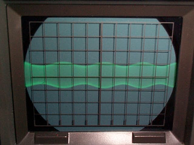
I
used a Kenwood SM-220 Station Monitor to observe the modulation depth. In NORMAL mode, the modulation depth would only reach about
30% maximum with a loud audio tone as shown in Figure
5. This is consistent with a statement in one of the EMERs
(Reference No. 7) that says "Modulated carrier will be in the order of
40%".
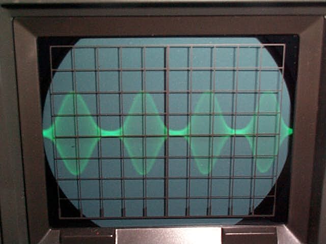
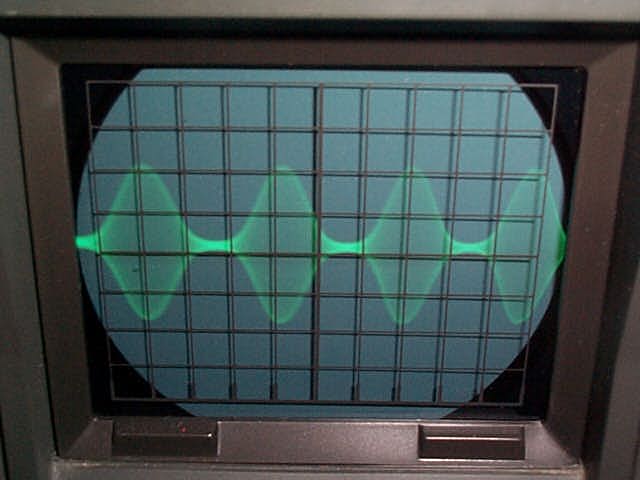
In
MOD 1 and MOD 2 position, Figure
6 and Figure
7 respectively, the modulation depth could easily reach 100% with the
possibility of over modulation with a loud tone.
The modulation depth showed about the same on both settings as you can
see. This is consistent with the on
air results with out-stations.
The
C.U. No. 10 in my collection was made by H.E.C.L. The inspection tag reads Chief
Inspector R.E.M.E. BX No. 034, 27 Apr 1965.
From
Reference No. 4 there is a Control Unit No. 10 MK 2 (ZA 10459) and a
modification for this unit is described as:
“On certain installations of the Wireless Set No. 19, using Control Unit No. 10, MK.2, a high pitched whistle is experienced, notably when sending with a Control Unit No. 2 switched to R-A and B. This is caused by the high level of side-tone on the Wireless Set No. 19 ‘B’ set. It can be prevented by reducing the output level of the ‘B’ set by connecting a 47 ohm resistor in series with the ‘B’ set output and another 47 ohm resistor in parallel with the lead to the phones.”
My
C.U. No. 10 has had this modification applied.
The difference between a C.U. No. 10 MK 2 (ZA 10459) and a C.U. No. 10
(ZA 10454) is not known.
There
appears to be a tropicalized version known as a Control Unit No. 10 MK1/1 (ZA
28564) as listed in Reference No. 8.
To
my knowledge the C.U. No. 10 was only made in England.
No Canadian-built versions are known to exist.
Conclusion:
This C.U. No. 10 is generally difficult to find on the collectors market. It has proven very useful for R/T contacts on the No. 19. It allows the facility of high-level modulation without modifying the No. 19 in any way.
References:
Return
to The Wireless Set No. 19 Homepage