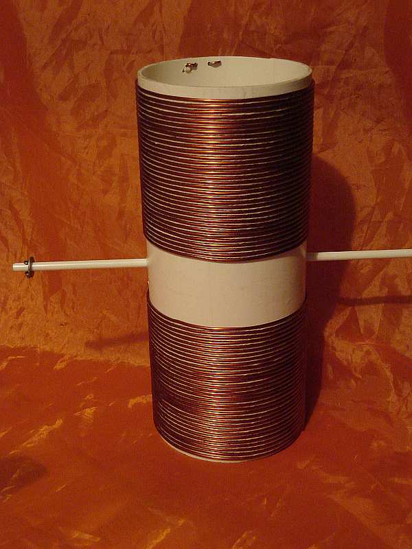
The
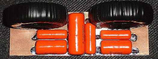
original loading coil had taps at the bottom but were later
replaced with a pair of computer flyback cores with 16T #16 en on the
secondary and 10T #14 stranded (PVC) over top on the secondary, then
wrapped with HV tape. The core was initially wrapped with a couple of
layers of HV white electrical tape 3M PN 69. The top of the
flyback secondary winding goes to the bottom of the big coil.
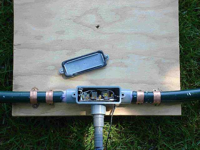
The
bottom of the primary was connected to
the braid of the RG8-X coax but not earth ground. The bottom
of
the secondary was connected to earth ground consisting of
two 5'
copper rods a few feet apart. As well, a few wires
leading
from the rods and buried just below the ground surface in the
back
yard.
In addition, a heavy copper wire is also connected to the
rods
and runs back several feet to another ground rod buried at the bottom
of a creek. For the loading coil, I chose a 320mm
(12.5")
dia form used for sewer applications. In the first
attempt
at matching, the bottom portion of the coil had taps every ~2
turns for impedance matching to 50 ohms, but is now replaced
with
a pair of flyback cores.
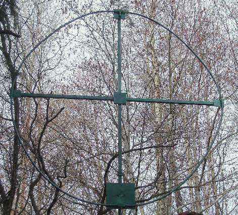
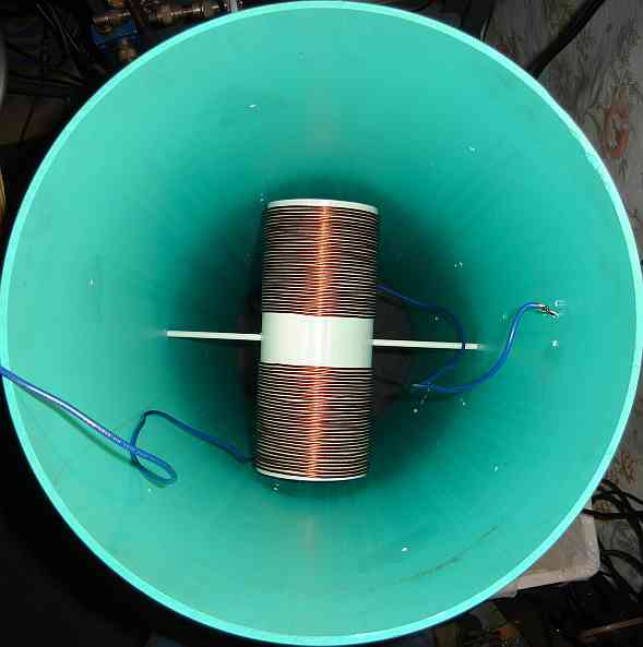
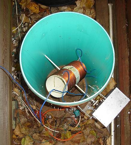
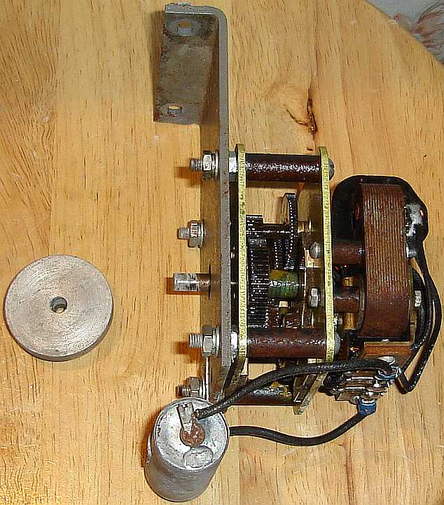
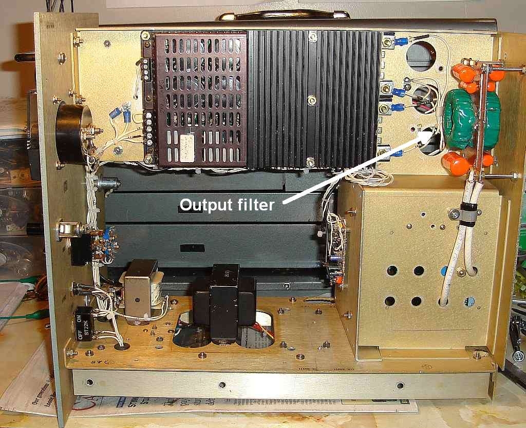
For fine tuning the larger coil, a variometer was
installed
inside the centre of the coil. The variometer had two coils
in
series, each having 33 turns and wound on a standard 4" dia PVC form,
10" long. The variometer either adds or cancels some of
the inductance to the antenna. At present, this
variometer
can be adjusted by remote control from the shack using a motor drive
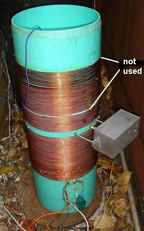
mounted on the outside of the larger coil. Initially the
large
coil had two sections each having 78.5 turns, for a total of 157 turns
of #14 AWG enamel wire, which later turned out to be too many turns and
I actually only needed ~104 turns, this gave me the best
resonance
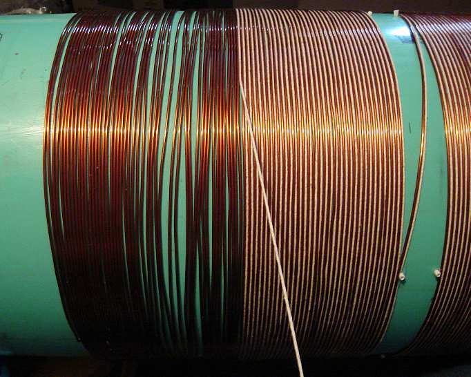
for ~137 kHz. The
large coil was wound on a 990mm (39") long form.
Each turn
was spaced 3mm centre to centre using cotton string. The
spacing
was to reduce the chance of arcing between turns as well increase the Q
of the coil. After completion of the winding of both coils,
three coatings of an exterior Varathane was added to eliminate any
absorption of the cotton to moisture. The large coil was
later covered by a blue PVC barrel to protect it from
the
weather. Don't use the black ones as they contain
too much
carbon and are too lossy.


