![]() 147.150+
& 53.150-
147.150+
& 53.150-![]()
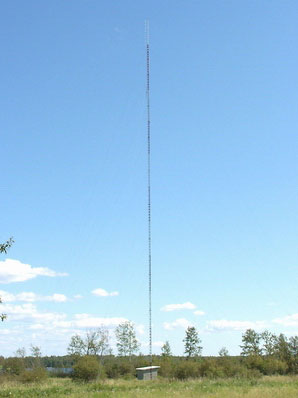
This is my 200' Beatty tower for the 2m and 6m repeaters. The 2 meter is VA3YHD, 147.150(TX), 147.750(RX) with a commercial Sinclair 210-C4 antenna at the top fed by Times Microwave LMR-600. The 6 meter repeater is 53.150(TX) and 52.150(RX) with 3-phased Decibel Products dipoles side mounted, top loop at 190' fed by Andrew's 7/8" Heliax.

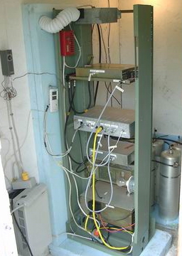
The 2 meter radio is a commercial Motorola MSR-2000 repeater, a 100 watt continuous duty transmitter. Duplexers are Sinclair Q-201G, 6 can pass, reject cavities with one additional pass cavity on RX . It is all run by a Link Communications, RLC-Club Deluxe controller and digital voice recorder. It has two full duplex ports to run both repeaters and can link the two together with the controller. The receiver pre-amp is an Advanced Receiver Research (SP144VDG).
The 6 meter repeater consists of a 6m, GE Mastr II 52.150(RX) and 53.150 TX 100 watt radio, with a set of modified Sinclair R101G reject (8 cavities) & 2 Sinclair pass cavities, 1 TX & 1 RX.
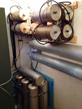
The duplexer system.
From the top is the 6M modified Sinclair R101G reject (8 cavities), with the two 6M Sinclair pass cavities mounted below.
Sitting on the floor is the Sinclair Q-201G, 6 can pass, reject cavities with one additional pass cavity laying on top.
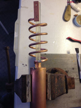
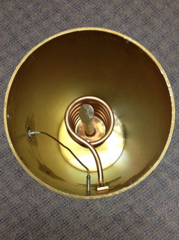
6 Meter Notch Cavity Mods

Showing inside & parts removed from 1 notch cavitiy. Had to modify all 8 cavities.
The inductor coil needed 1 turn removed from the original 6 turns, to increase frequency to 52-53MHz.
I used a dremel tool with cut-off blade to cut inductor tubing.
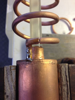
Then I folded some #10 AWG wire, inserted into the tubing, to strengthen joint before soldering.
Used a propane torch to solder the joint.
It was very difficult, had to feather the flame in & out. It would over heat easy, causing solder to run away.
As you can see, the silver coated tuning stubs where very corroded & needed Silvo to clean.


All cleaned & re-assembled, ready for tuning.
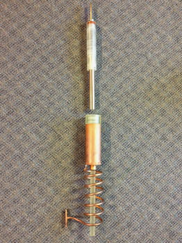
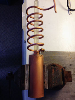
6 Meter Pass Cavity Mods
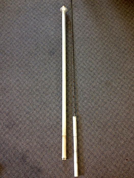
Before removing the internal parts from the cavity, I measured the original high & low frequency range by sliding the movable plunger from top to bottom while measuring the frequencies. Then measuring the plunger after disassembly, I calculated that by removing 5" from the fixed tuning plunger would increase the frequency to 52-53MHz that I needed.
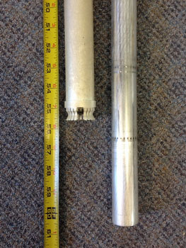
On the left is the fixed tuning plunger & movable tuning plunger removed from cavity, on the right the original measurement of the fixed tuning plunger.
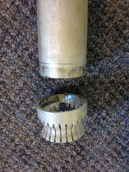
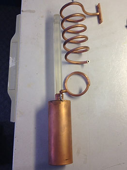
I noticed that the finger-stock as held on by a compression ring of a larger diameter over the fixed tuning plunger.
I just tapped it off & the finger-stock was wedged in-between the two pieces. I measured 5" and shortened the fixed tuning plunger with a good pipe cutter.
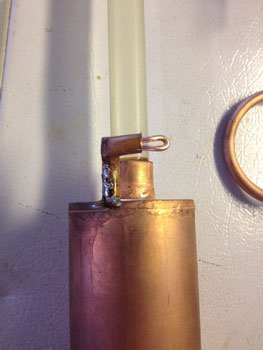
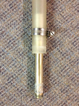
Then I had to step down the outer diameter of the fixed tuning plunger to accept the finger-stock & compression ring.
After that, cleaned all surfaces, tapped the finger-stock & compression ring back on. Then soldered for mechanical & electrical purposes.
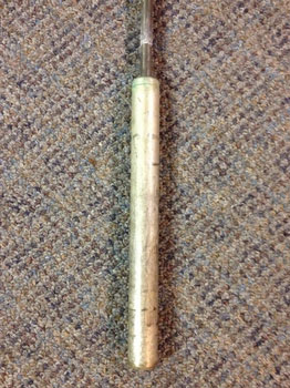
After tall that, I cleaned the movable tuning plunger & finger-stock with Silvo before re-assembley.
All ready to be tuned & install in repeater shack.
Check this Adobe .PDF document for 2m duplexer tuning- by VE3MOR & VA3EXT 18.5K.
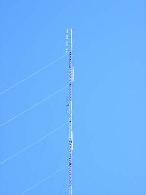
![]() Visit "Up
Tower" for pictures from the top of the 200' tower.
Visit "Up
Tower" for pictures from the top of the 200' tower.![]()
![]()