|
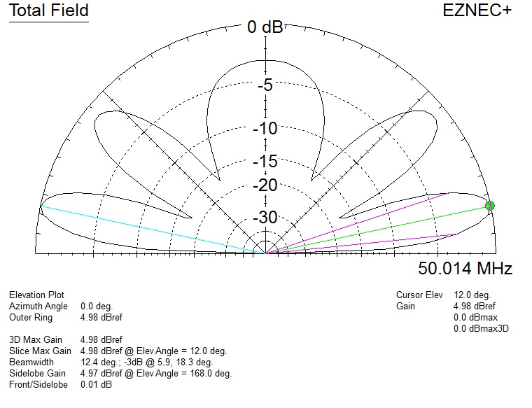
I stacked a set of M2 HO Loops
for the V73SIX Beacon Project.
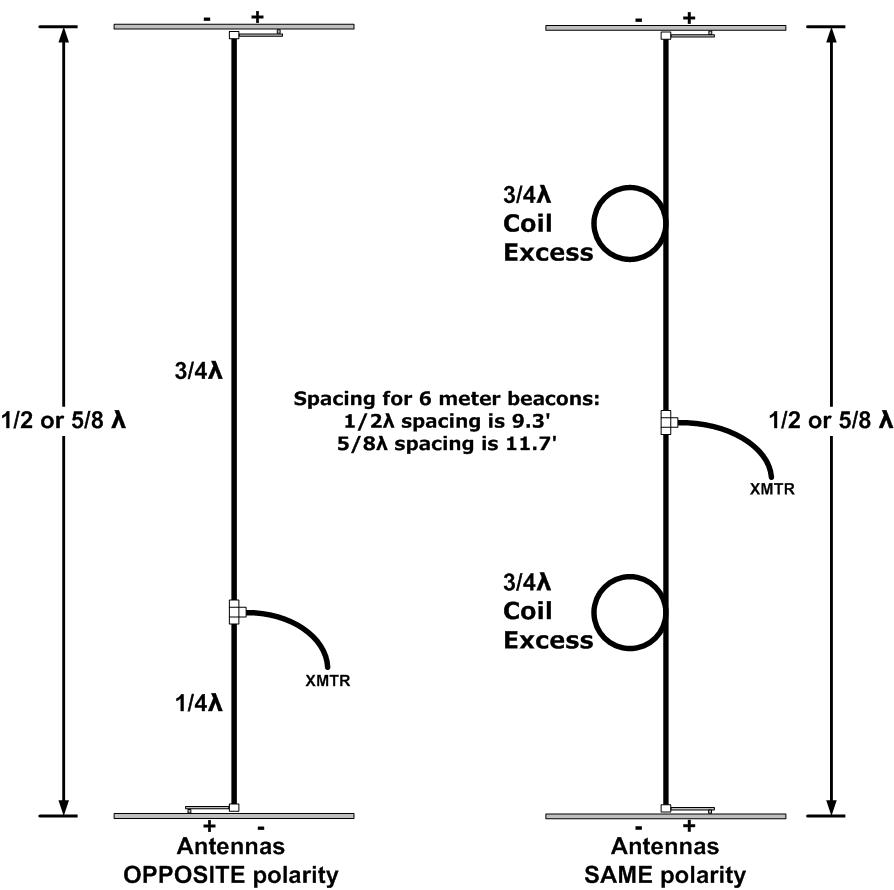
Stacking Distance
Just as in building a dipole this spacing is easy to calculate with 468 / Frequency (MHz). My target frequency is 50.012 and the 1/2 wave spacing is 9.3 feet. The 5/8 wave spacing for that frequency is 11.7 feet.
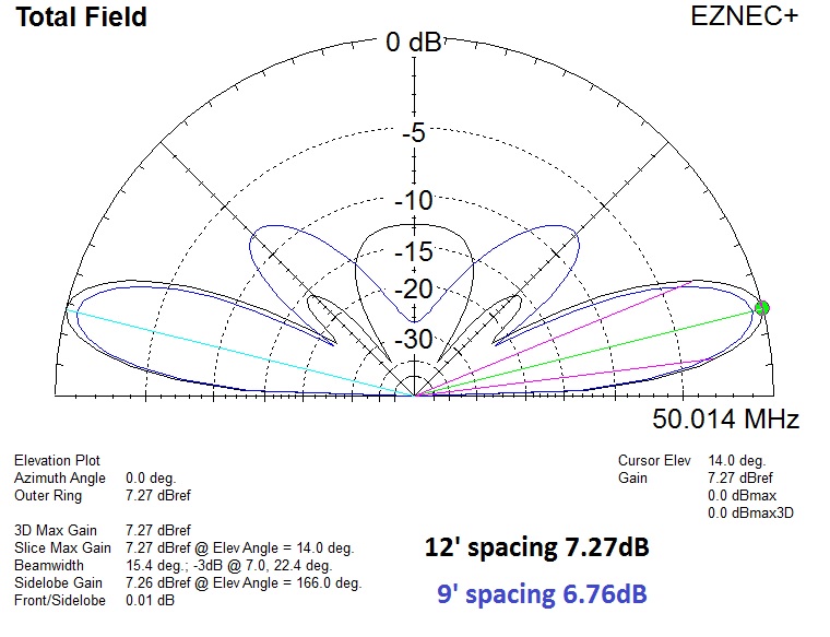
5/8 wave spacing adds ~.5dBd of gain. If you have the vertical space on the mast for 6 meters it's your choice.
Stacking Harness
Feeding two 50 ohm antennas requires a harness to divide the power between the two antennas and also to maintain a 50 ohm system. To do this, each leg of the harness needs to be 1/4λ (or odd multiple of a 1/4λ) long of 75 ohm coax. Since we are dealing with coax cable these calculations need to include the velocity factor to get the proper length cables.
To find a 1/4 wave of coax use the formula below.
* In Feet: 246 x (Velocity Factor) / Frequency (MHz) = Length in Feet
* In Inches: 2952 x (Velocity Factor) / Frequency (MHz) = Length in Inches
To find a 3/4 wave of coax use the formula below.
* In Feet: 738 x (Velocity Factor) / Frequency (MHz) = Length in Feet
* In Inches: 8856 x (Velocity Factor) / Frequency (MHz) = Length in Inches
Two ways to build a harness
1) You can build a harness using a ¼λ and a ¾λ length. Be aware that if this type of harness is used the feed point of one of the antennas will need to be opposite polarity. If your antenna is a HO loop, one block should be rotated so that the “hot” side is the opposite direction. In the case of HO loops, you will also need to point the connector up to allow for enough cable length.
2) You can build a harness with two ¾λ sections (as I did) and keep the orientation of the antenna feeds the same.
Why use two 3/4λ lines?
I wanted to stack my antennas with 5/8λ spacing (~12 feet). Two 3/4λ sections of RG216 yields more than enough cable for either stack spacing selected. I also do not like the idea of the coax connector pointing up. With a longer cable they can both face downward. Why didn't I use RG11? Well, I live on a remote island and I had a piece of RG216 handy.
The 75 ohm cable that I selected is RG216 (VF of .66) which is .425 inches in diameter, slightly larger than RG11 which is .405 inches in diameter. N connectors are the only logical choice for these cables as the jacket does not fit into the PL259. Since the HO loops have SO-239's, an adaptor is used to make the transition.
My 3/4λ lines are 738 * .66 / 50.012 = 9.74' (116.88") each and I accounted for the length of the finished cables with connectors / adaptors installed.
Remember to get the correct velocity factor for the cable which you use to make the stacking harness. RG216 has a VF of .66 while RG11 comes, depending on the manufacture, with a VF between .66 and .84 and it does make a difference. A cable made with .66 VF line is 2.6' shorter than a cable made with .84 VF!
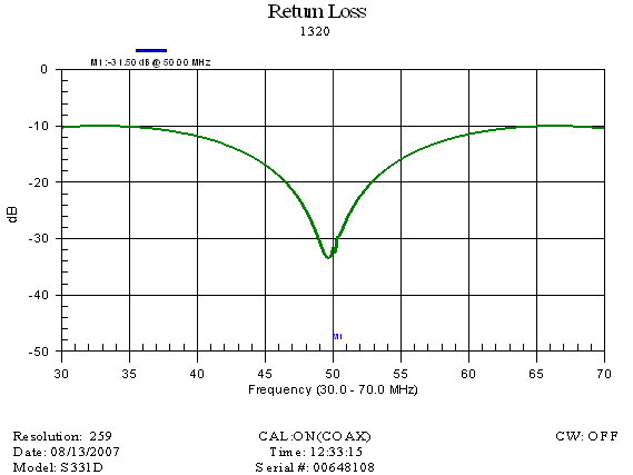
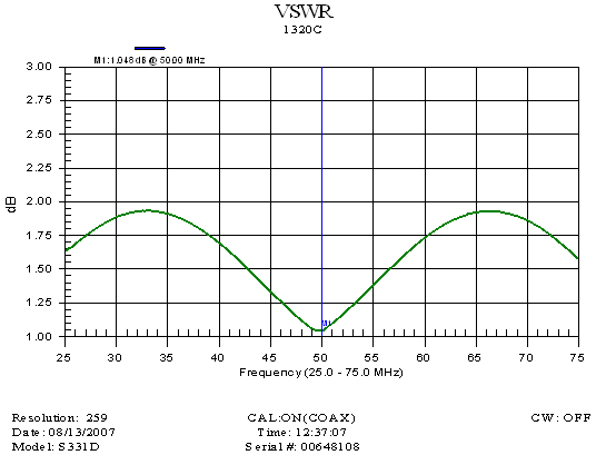
Below are some plots I made of the harness with an Anritsu Site Master tester. It's not as full featured as the HP Network Analyzer, but it is light and easily transportable and ideal for this project.
|