Island Tuner
Years ago a friend offered me some parts he started to collect to build a transmatch, which he never got around to building. I added to the collection a band switch, vernier drives, ceramic insulators etc and then, like him, I stored the parts and they sat. And they moved around the world a couple times and sat some more.I finally figured it was time to get something built.
Tinkering is always a fun thing to do and so is planning a project. I have a selection of parts and can configure my new tuner in one of three ways;
1) Ultimate Transmatch Network (W1ICP circa 1961) with split stator capacitor on the input (similar to the Heathkit SA-2040)
2) SPC Transmatch (W1FB circa 1981) with split stator capacitor on the output.
3) Classic T Network (Heathkit SA-2060)
The Ultimate Transmatch design has some drawbacks at high load impedances where minimal output capacitance would be in shunt with the inductor, giving rise to a high-pass condition. This design fell out of favor to the T and SPC.
The SPC Transmatch configuration addressed this as there is always some capacitance in parallel with the inductor (and a bit of loss as a result). It also has a greater frequency range than the Ultimate Transmatch using the same components, requiring less inductance and less capacitance. The SPC also has better slightly better harmonic attenuation than the classic T Network.
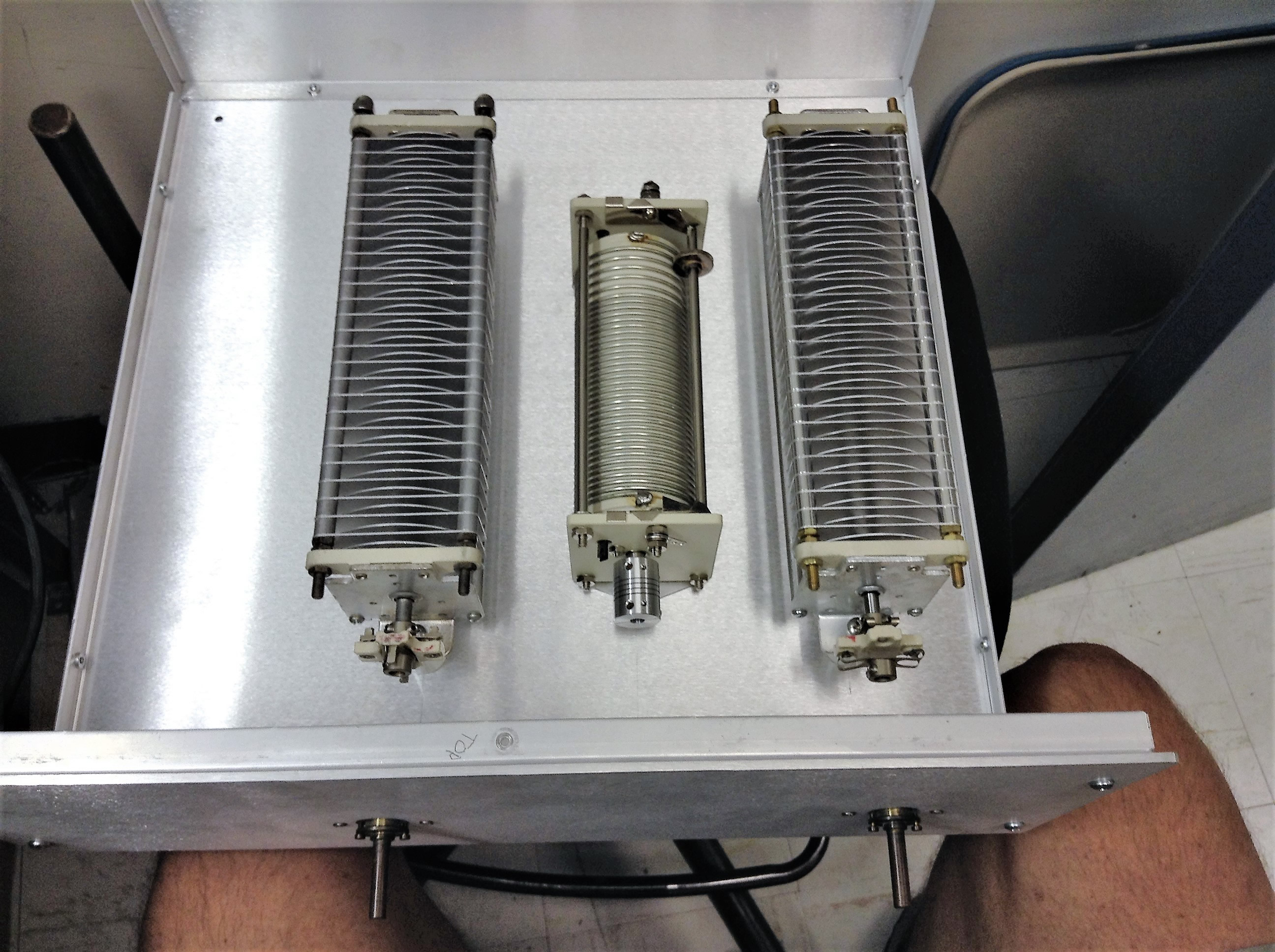
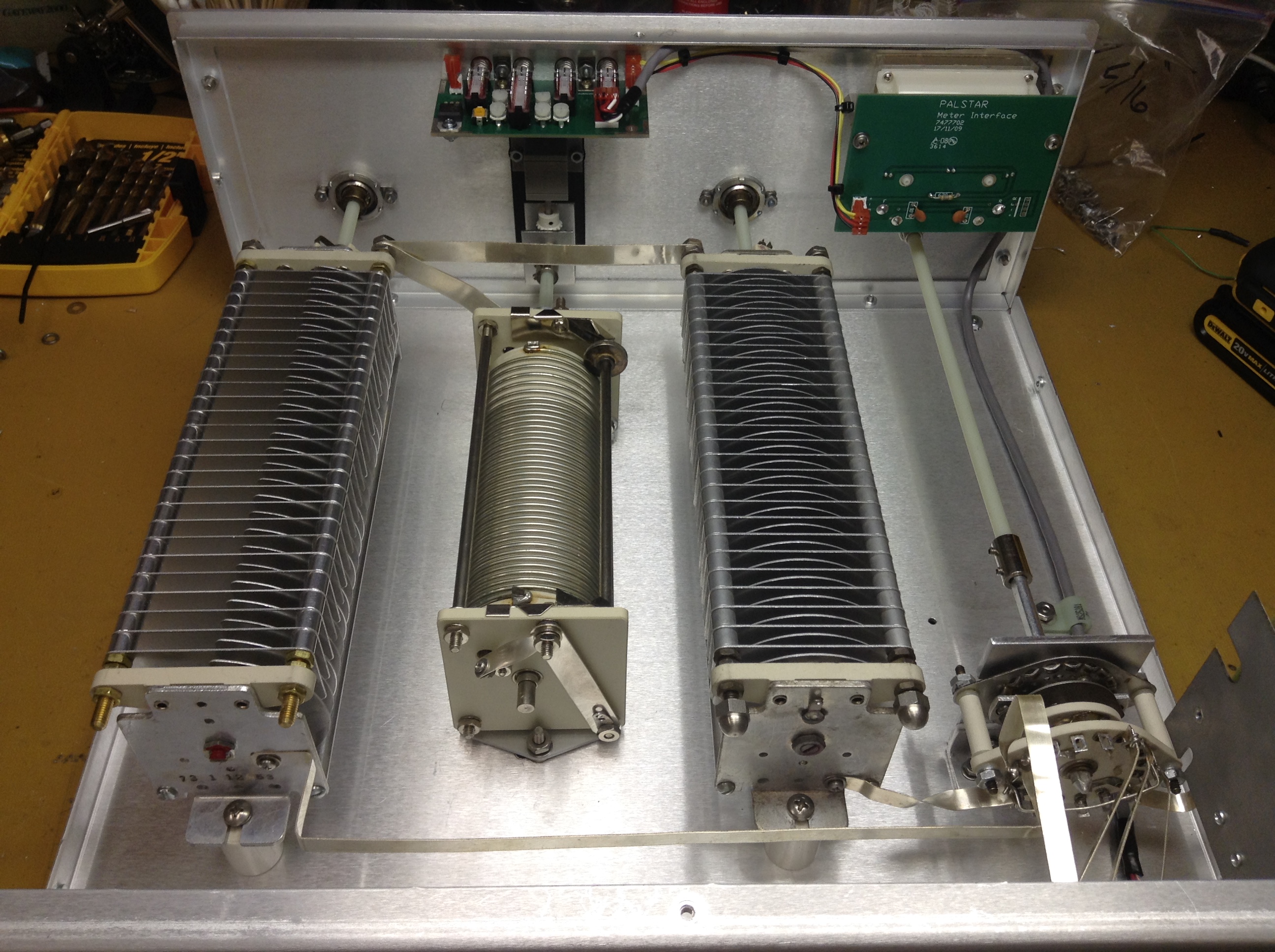
The Classic T Network is a time proven design. I am blessed with a 28µH roller inductor and two 250pf caps as well as a split stator cap so my options are open. The two modern day commercial choices are a toss-up between the Classic T and the SPC. I will build the Classic T.
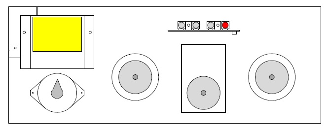
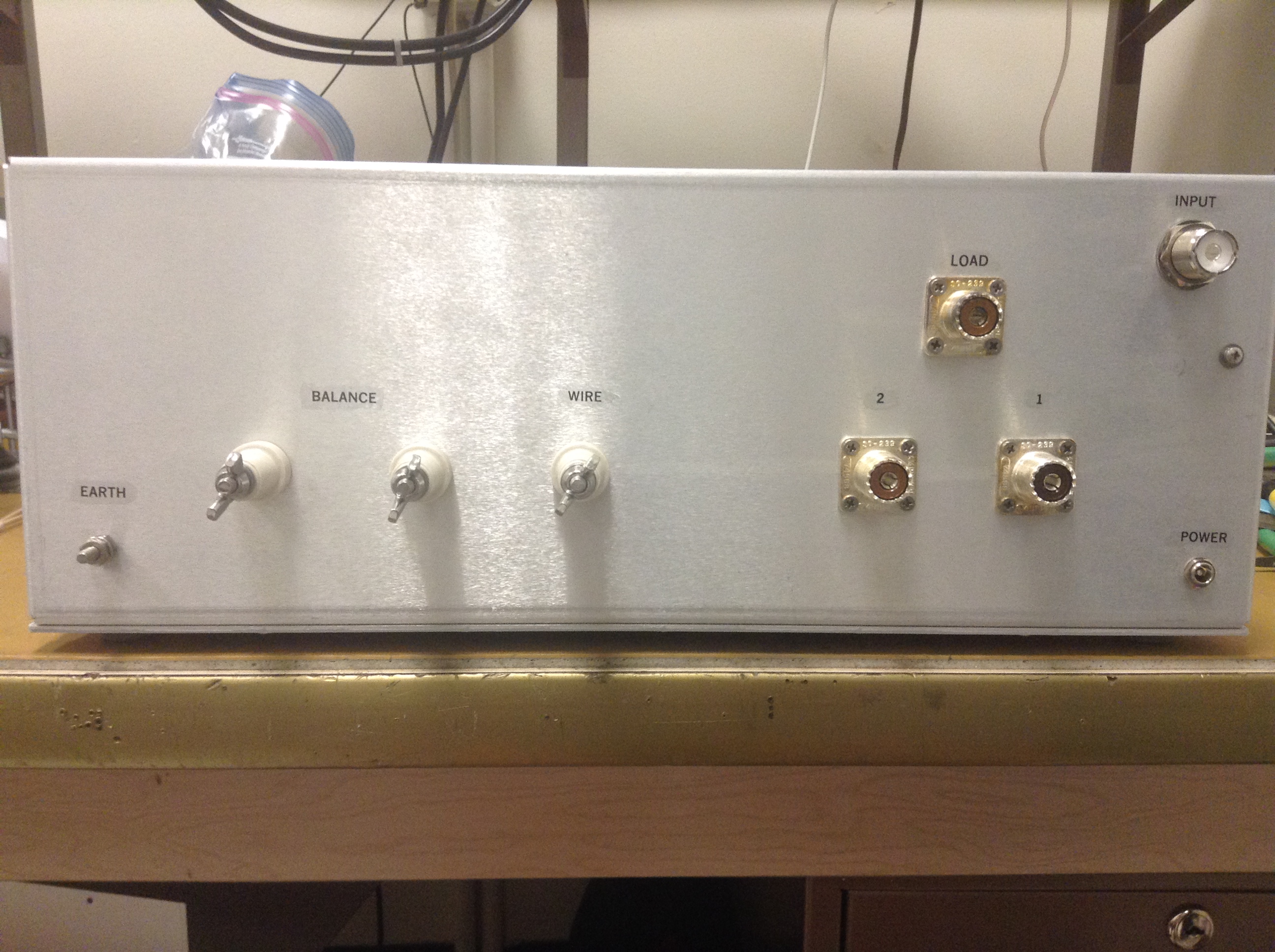
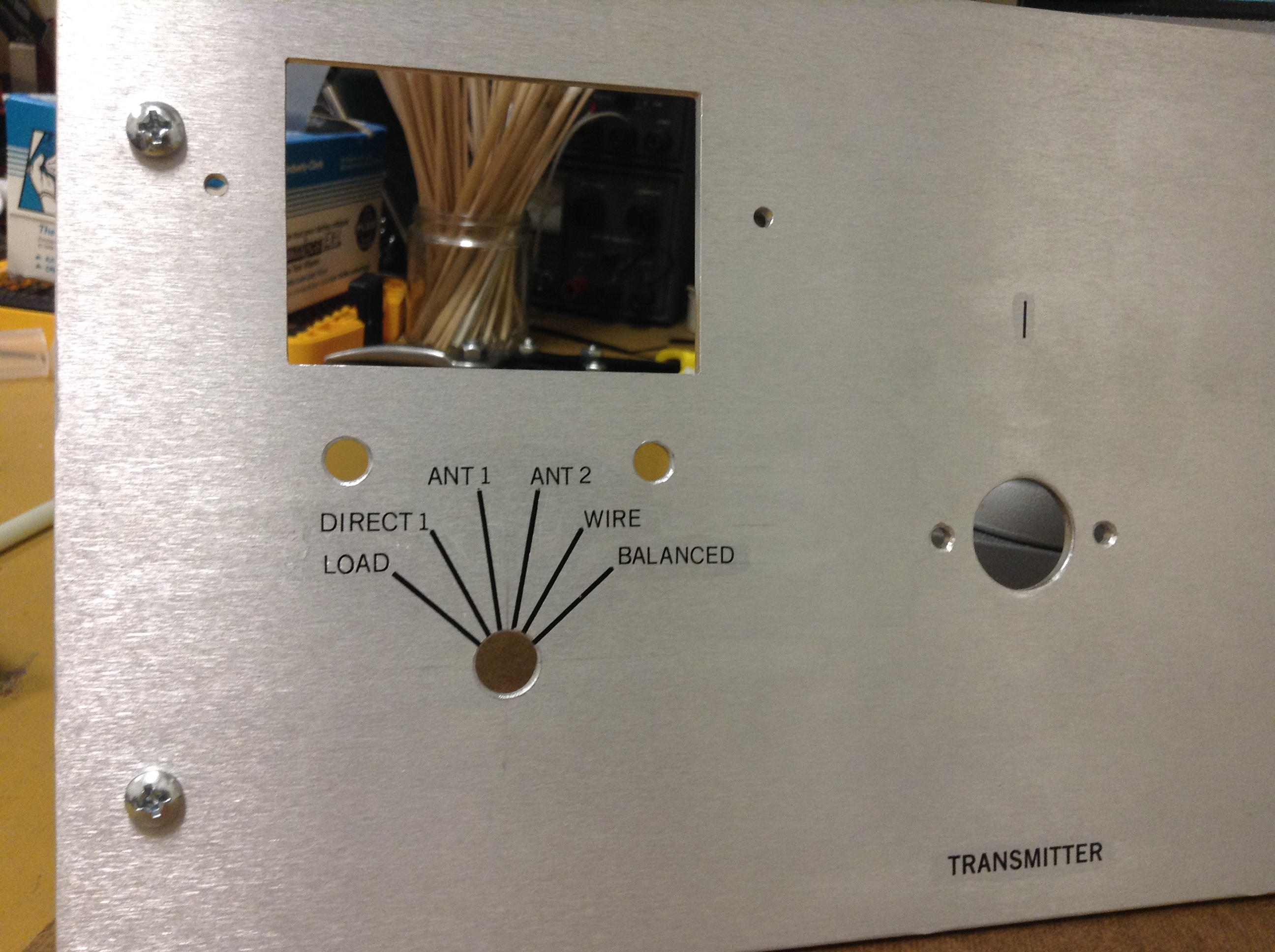
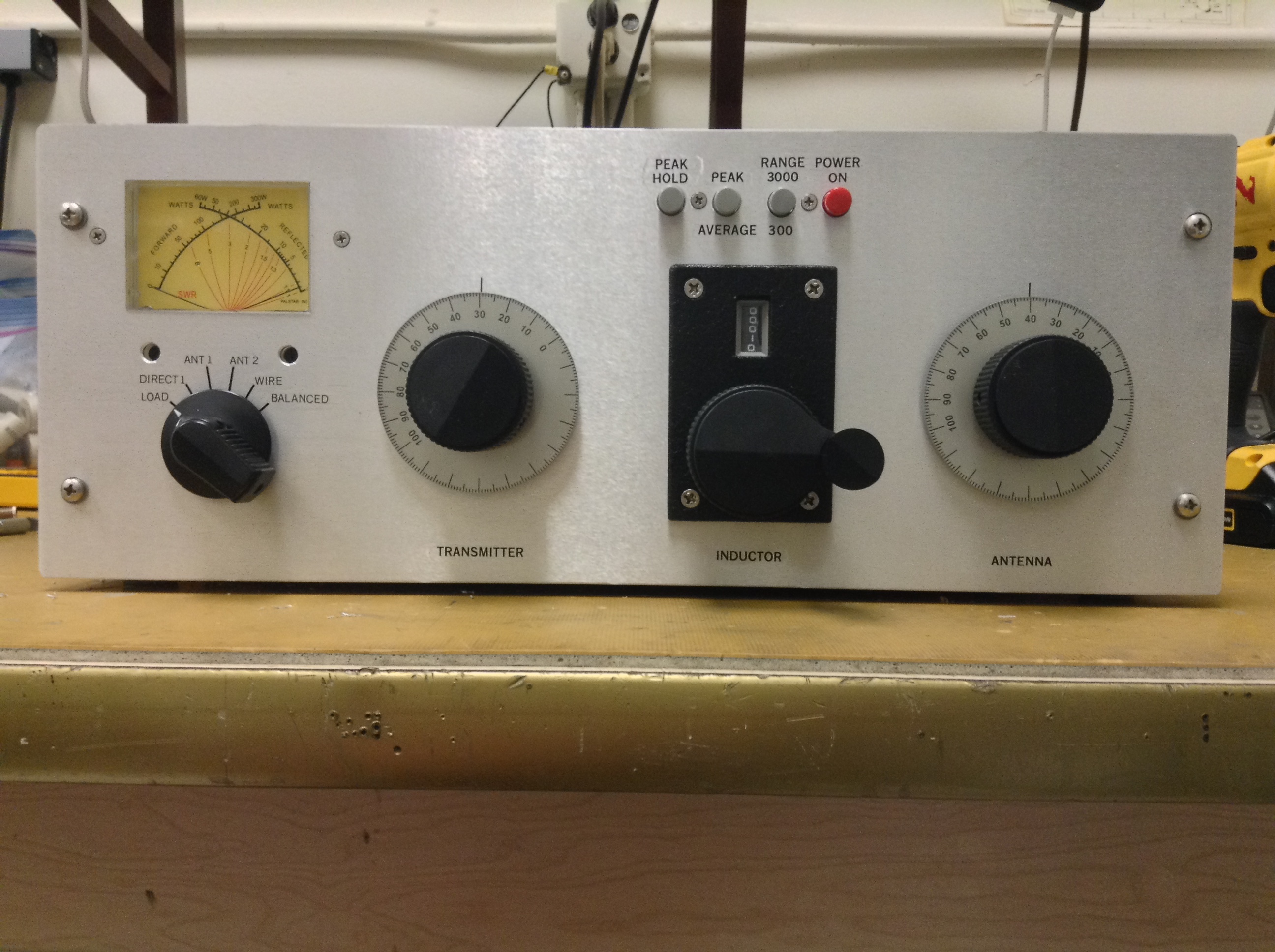
On to the design. I want my tuner to have an antenna switch which allows selection of a dummy load, two coaxial outputs (Ant 1 and Ant 2), a longwire output, a balanced output and a direct position for coaxial Ant 1.
I want to have an internal SWR and Power indicator. For this I purchased the needed parts from Palstar, which sells a directional coupler, dual needle meter and meter board. Those will be incorporated in my tuner so I don’t need an external meter. Using a commercial product also saves me the hassle of sourcing the correct parts and reinventing the wheel and is far more accurate than anything I'd build.
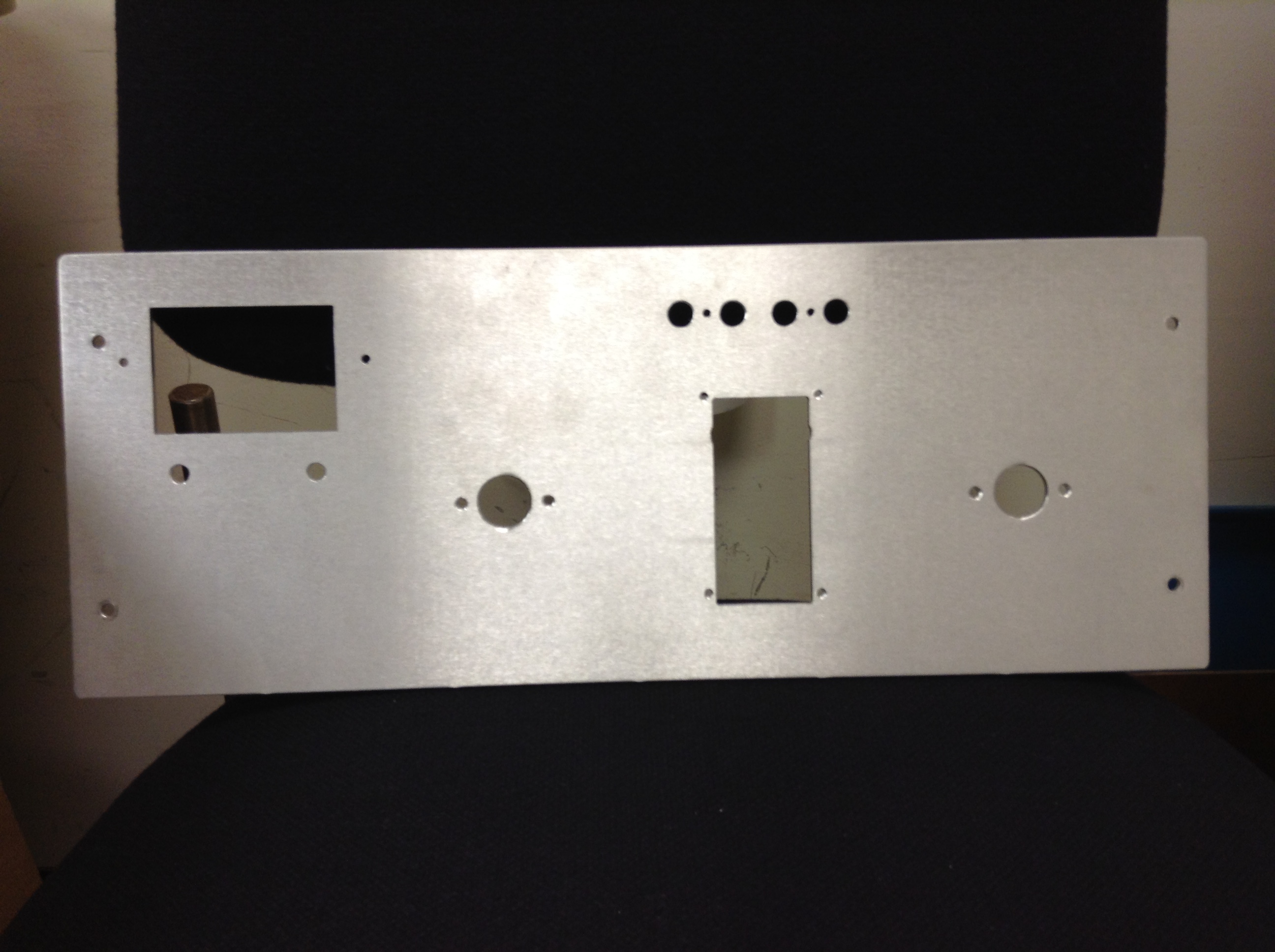
Suitable enclosures are one of the hard things to source. I don’t want to cram everything into a small case. Doing so would cause unwanted interaction with the case and I want things spaced out nicely. Minimum case size would be 5.5H x 14W x 14D, which is roughly the same size as thee Heathkit SA-2060 enclosure. I also do not want to work inside a box as the metal working becomes a challenge. I have a rectangular hole to cut for the SWR/Pwr meter and inductor turns counter and want the front face removeable to facilitate machining.
Bud makes cases but are a bit pricey. I found PAR Metals makes a nice Series 20 case that would fit my design at a slightly lower price than the Bud. It is 6” high, 16” deep and 16” wide. It is p/n 20-16166NM. Natural finish and no holes in chassis.
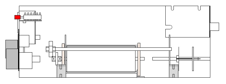
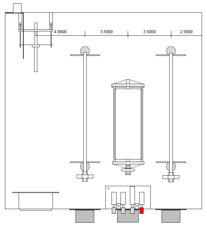
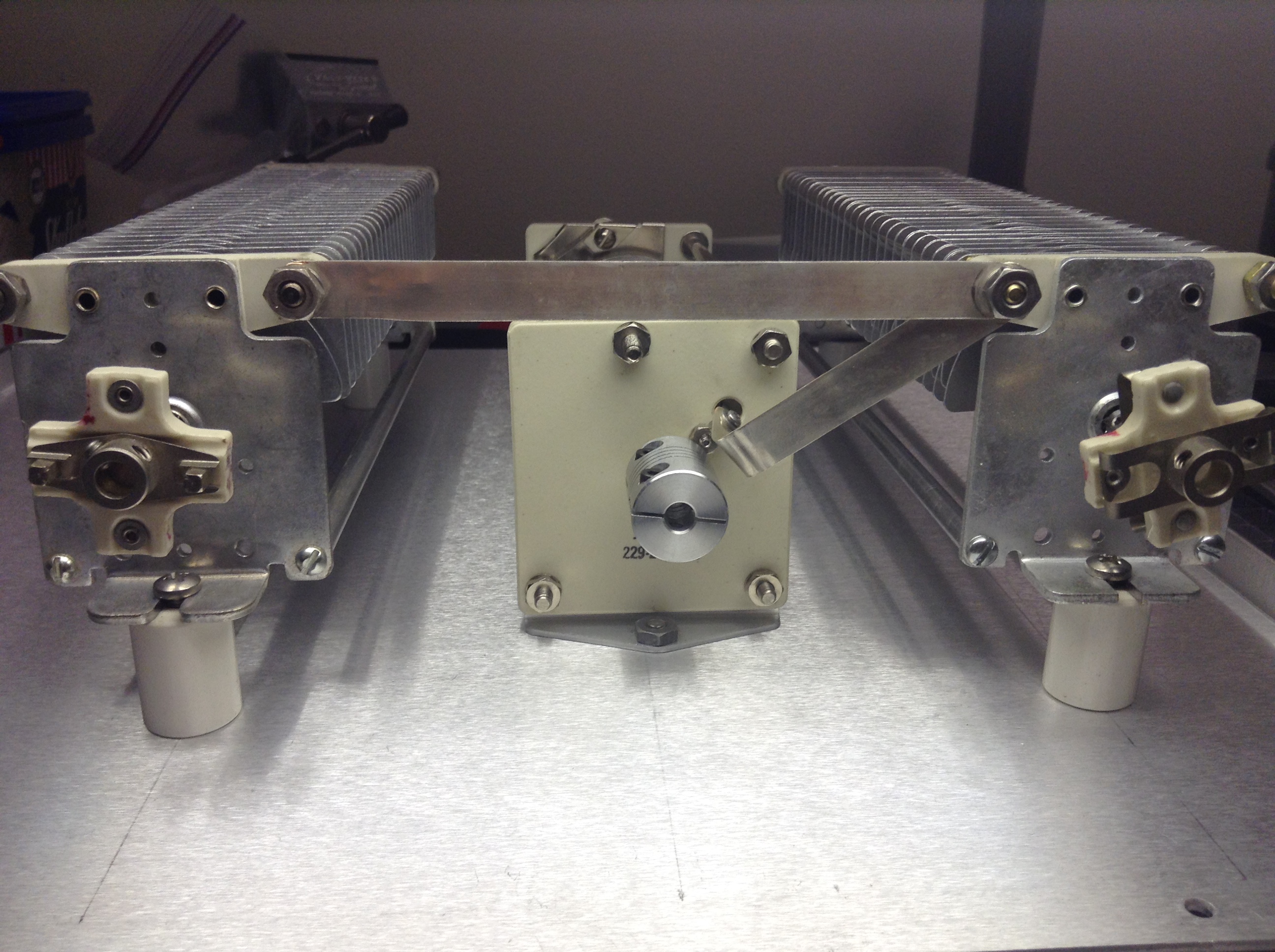
Laying out the design is an easy thing these days with desktop software like CAD and Visio. I used Visio for my layout. The first task was to make rotation drawings of each of my components. These do not need to be highly detailed, but represent the overall dimensions, mounting holes, shafts and connector clearances. A detailed drawing of the case was also made, including panel thicknesses and clearances. Together with the component drawings I can lay it all out and see how everything fits. From this I can also later produce my drill and machining drawings. Measure twice and cut once as they say.
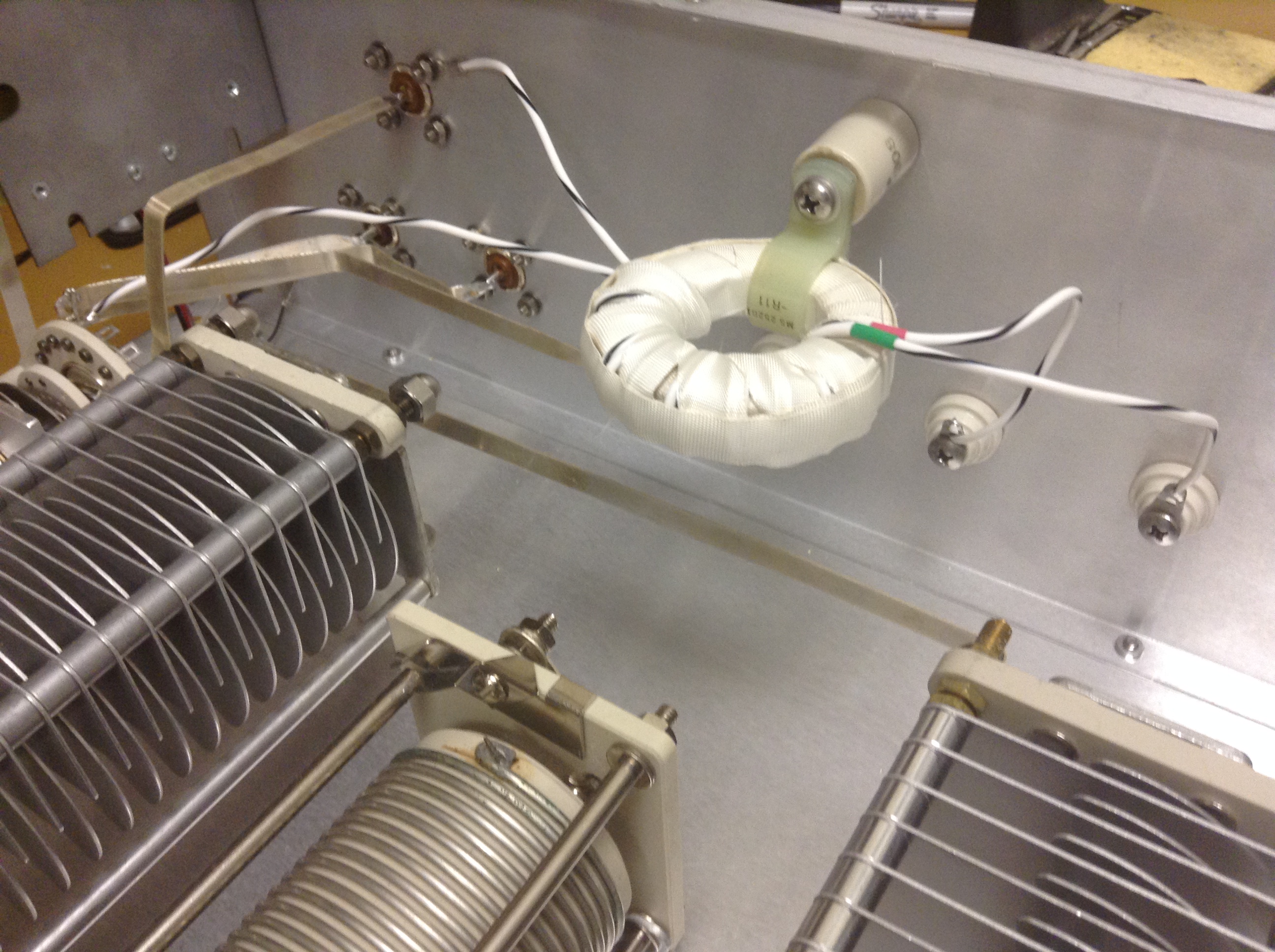
An internal balun is desired as I want the balanced output option. Here is where the debate is. Old school designs have 4:1 baluns, as do many modern ones. If you are using a single antenna as a multiband antenna the actual impedance which a 4:1 balun might see on some bands could be something like 10 ohms. That means your tuner would be presented with a 2.5 ohm load. Unless you know your system is a 200 ohm load, using a 1:1 balun is a more logical choice.
Palstar tuners often come without internal baluns in their lower tier manual tuners. The Palstar AT4K and AT5K have a 1:1 balun on the input, which some think is wise, but they should still be on the output. Tom, W8JI, has an excellent write up on this. Baluns should be on the output side of the tuner.
I am toying with the idea of having two balanced outputs on the rear apron. One with a 4:1 balun and one with a 1:1 balun. I have the feed-thru insulators, I’d just need an extra toroid.
|