V73NS and the
G5RV Antenna
There is a lot written and said about the G5RV antenna...
I used a G5RV here from 2003 until 2008.
Is this a secret weapon?
No.
Is it the best antenna you can put up?
No.
Does it work, yes.
It is a great multi-band antenna that does not use traps, takes advantage of "long" length, works for DX and is intended to be used with a transmatch.
(NEW HAMS: Antenna tuners are located at the antenna, a transmatch is what sits on your desk indoors. There is a difference!)
The idea of using ladder line as a transformer is not new by any means. This antenna, in the 102' length, is designed to perform well and offer multi-band operation while offering the ease of using coax to feed it.
You will see some call for the ladder line used in the matching section to be 300 Ohm... yes, you can build it with that, but 450 ohm line is more common these days and closer to the homebrew line Louis used, which was around 525 ohms. With 450 ohm line you can also use the popular "Ladder Lock" center insulator and save the hassle of coming up with something on your own.
No matter what line you use... you can calculate the length of it as follows.
THE MATCHING SECTION:
Due to the standing wave on it, the actual impedance is unimportant. The matching section should be made from window-type open wire line, either 300-ohm, or 450-ohm.
You can build your own open wire line as Louis did using 16 AWG wire, spaced 2 inches apart.
The least desirable is "TV- type" twin lead due to the high losses and the poor mechanical construction of the line.
MATCHING SECTION LENGTH:
The length of the matching section is an ELECTRICAL half-wave on 14 MHz. The actual physical length is determined by the following formula:
L= (492 x VF)/f (MHz), where VF is the velocity factor of the matching section.
The velocity factor is determined by the type of line, and the dielectric properties of its insulation. For the three types of line discussed so far, the VF is:
Open wire - .97
"Window" line - .90
"TV" twin lead - .82
DO NOT FEED THIS WITH A VOLTAGE OR CURRENT BALUN!
A simple coax to ladder line transition is all that is required at the feedpoint. A Series Balun (ferrite beads over coax) is fine or a few turns of coax to decouple the line.
Adding a balun to this point increases losses and can be damaged by heating effects if you operate with an amplifier.The ladder line IS the impedance transformer... it doesn't need another one, so forget about adding a 4:1 too!
The full-sized G5RV antenna was NOT designed as a half-wave dipole on the lowest frequency of operation, but as a 3/2-wave center-fed long-wire antenna on 14 MHz, where the open-wire matching section functions as a 1:1 impedance transformer.
This enables the coaxial cable feeder, to see a close impedance match on that band with a consequently low SWR on the feeder. However, on all the other HF bands, the function of this section is to act as a "make-up" section to accommodate that part of the standing wave (current and voltage components) which, on certain operating frequencies, cannot be completely accommodated on the flat- top (or inverted-V) radiating portion.
The design center frequency of the full-size version is 14.150 MHz, and the dimension of 102 ft is derived from the formula for long-wire antennas which is:
LENGTH (ft) = 492(n-.05)/f(MHz)
= (492 x 2.95)/14.15
= 102.57 ft (31.27 m)
where n = the number of half wavelengths of the wire (flat-top)
"Because the whole system will be brought to resonance by the use of a matching network in practice, the antenna is cut to 102 ft."
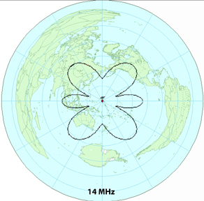
As the antenna does not make use of traps or ferrite beads, the dipole portion becomes progressivily longer in electrical length with increasing frequency. This effect confers certain advantages over a trap or ferrite-bead loaded dipole because, with increasing electrical length, the major lobes of the vertical component of the polar diagram tend to be lowered as the operating frequency is increased. Thus, from 14 MHz up, most of the energy radiated in the vertical plane is at angles suitable for working DX.
Furtermore, the polar diagram changes with increasing frequency from a typical half-wave dipole pattern at 3.5 MHz and a two half-wave in-phase pattern at 7 and 10 MHz to that of a long-wire pattern at 14, 18, 21, 24 and 28 MHz.
On 14 MHz the use of 50-ohm coaxial cable results in only about a 1.8:1 SWR. The use of a suitable matching network is nessessary, but the antenna performs well on 80 through 10 meters. The G5RV does present some impedence challenges on 30 meters, but still performs well.
My installation has the G5RV at a height of ~20 meters, between two telephone poles. It runs north south and the patterns produced are ideal to cover NA, SA, EU, AF and OC.
Still think the G5RV is a terrible antenna?
Maybe it is for your location, but not for mine. Listen to my signal and judge for yourself.
Here is the 14 MHz plot for my G5RV's height and orientation on a great circle map.
As you can see, it's an ideal antenna for me.