Making the Astron SS-25 "Shack Friendly"
V73NS
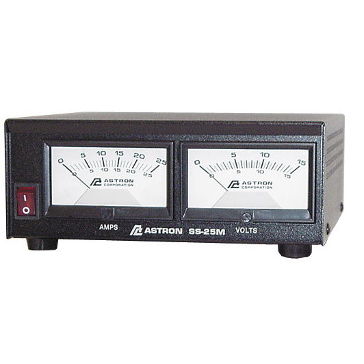
I purchased an Astron SS-25M in August 2014 and set out to make it fit my needs.
As with all projects of this sort, you do this at your own risk, it voids the warranty, it could cause damage to the power supply, the equipment attached to the power supply, and surrounding property. Does not contain peanuts. Do not use in the shower. Not to be thrown at people or animals. Keep away from pets, infants and bad advice and be sure to unplug it first etc etc.
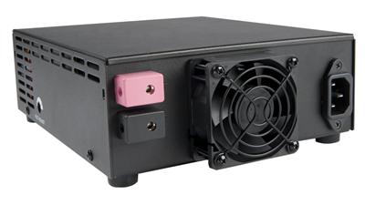
The SS-25 uses Torx screws on the case, which are a pain if you do not have the correct tool to remove them in the field. They require a TX-9 tool. Once I removed them I replaced them with Philips head hardware so that I can access the guts anywhere, not just in my shop. The design has changed a bit, the input voltage selection switch is no longer required and it covers 115 VAC 50/60HZ
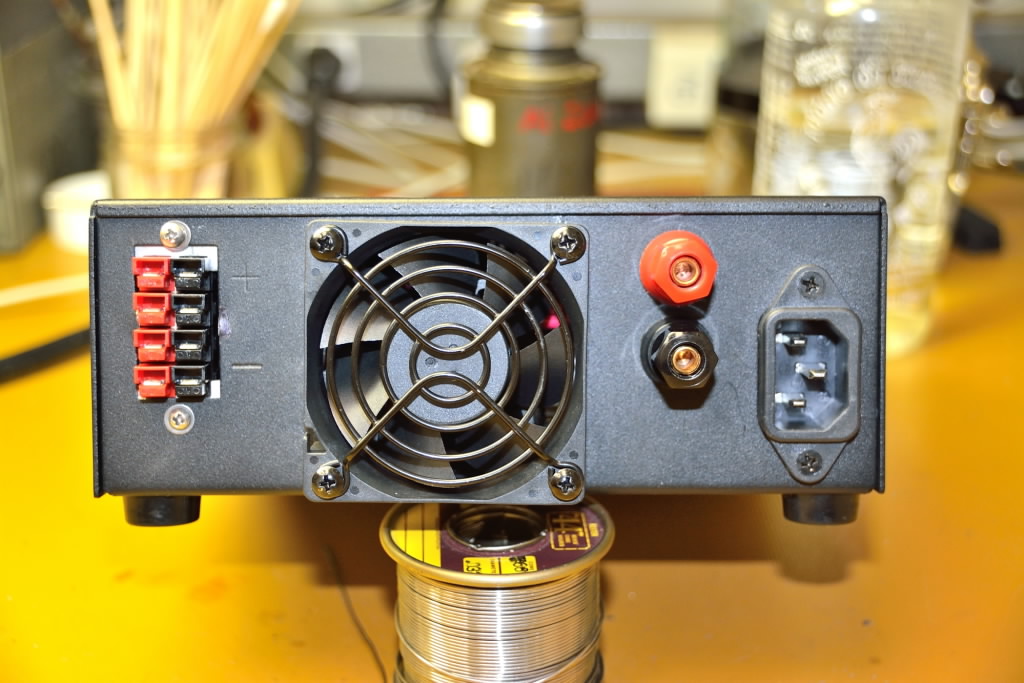
or 220 VAC 50/60HZ as delivered. I'll travel to Asia with this so that's a real plus. There are no pre-punched knockouts on the back either.
(My Samlex requires an internal jumper ...which I must remember to do before plugging it in or risk damaging it)
A schematic was NOT included with the unit - which seems common for Astron these days.
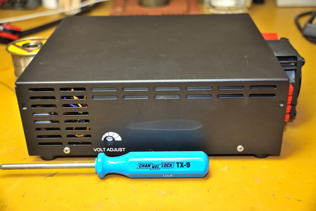
Case with Philips rather than Torx hardware
The factory terminal connections on the SS-25 are terrible and going to be removed and discarded. In their place will be four Powerpole connector and on the other side of the case I added a set of binding posts to allow me to have options for how I use this supply in the future. Note; spacing the binding posts at 0.750” allows them to accept molded double banana plugs, so keep this in mind.
Remove the factory terminals by first removing the wire from them and then to make their removal quick and painless, cut off the ears on them and they come right out. Place them straight in the circular file.
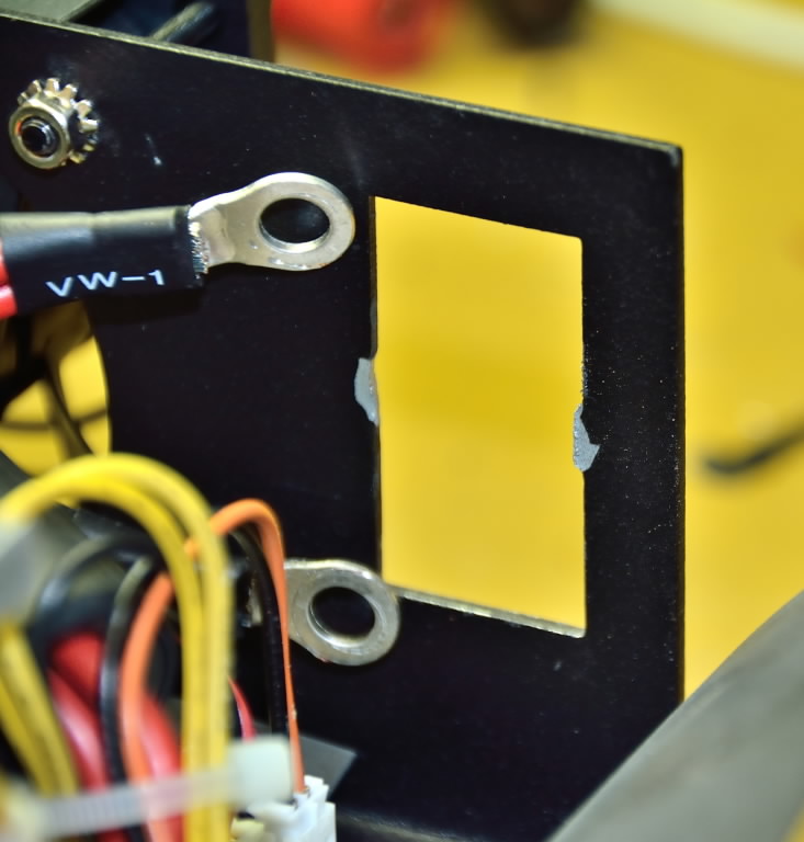
Factory terminals and bridge removed
Between the factory terminal holes is a small strip of metal that will need to be removed. It cannot be twisted out and needs to be cut out. I used a Dremel tool to do this, making it a large rectangular opening which will be filled by the powerpole connectors. The hole is oversized so fitting the new connectors in will require the use of two mounting clips, available from Powerwerx. These are held in place with machine screws and nuts. Place three of the roll pins supplied with the powerpole connectors in the stack and when installed in the clips they will span the mated connectors and make a nice solid assembly.
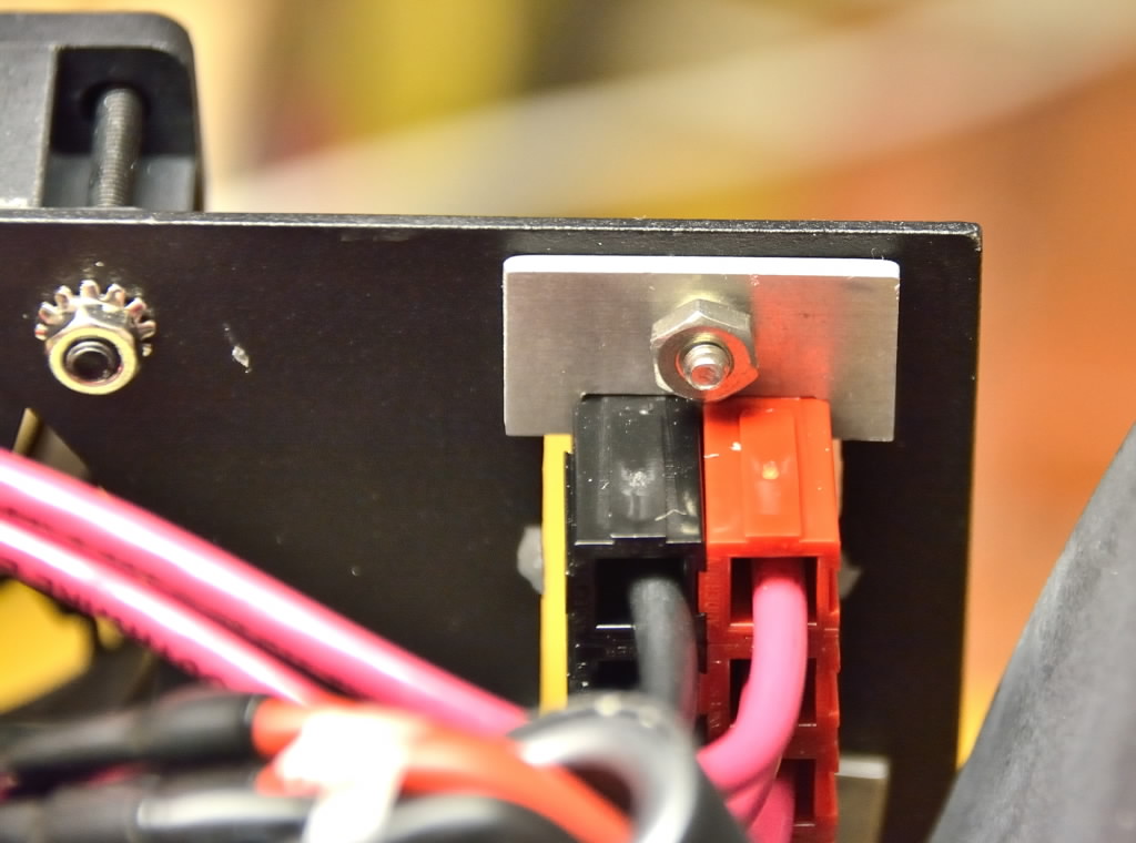
Powerpole connectors held in with mounting clips
Binding posts are installed between the fan and the AC power connector. I wanted the standard 3/4” (0.750) spacing on them so I can use any standard double banana plug. Depending on the binding posts you use there may well be a clearance issue with the heatsink at the back to the circuit board. I ground off the solder terminal and a 1/8” (0.125) of the thread which gave me enough clearance once assembled to clear the heatsink. Since it’s DC voltage a small spacing is all that is required. As you'll see in the last photo I could have come up a tiny bit, but either way it was going to be too tight. NOTE: When selecting your binding posts keep in mind that you'll have three ring terminals and one washer on each one of them!
(HINDSIGHT - I could/should have installed the binding posts horizontally and avoided the heat sink, and likely would if I had to modify another one.)
NOTE: I did modify a second unit and did install the binding posts horizontally. Of the two, I would still opt for a vertical mount as the wiring is neater. April 2015
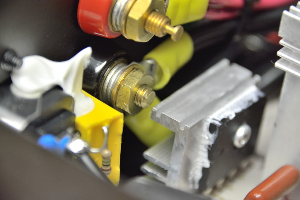
Trimmed stud
Since the factory terminals are gone, the original wires have nothing to connect to. These will be lengthened and run to the binding posts which will also serve to connect the Powerpoles.
Using 12 gauge wire, prepare wires ~8” long with Powerpole terminals on one end and stuff them into the housings before installing the housing assembly in the back panel. Once installed, I routed them over to the binding posts and cut them to length. Crimp/Solder two wires into each ring terminal that will connect to the binding posts.
Again, using two 12 gauge wires in a ring terminal, make a set of wires to connect to the binding posts and reach over to the original wires. I removed the original ring terminals and soldered my extensions to them and covered the joint with a high quality heatshrink tubing.
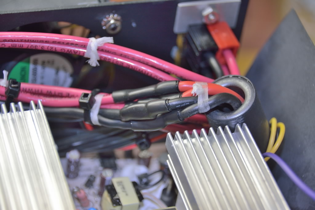
Spliced original leads
Clean up, tie up and be sure all metal/solder debris is removed from the inside of the case and you’re ready to button up and enjoy. Remember to replace the original Torx hardware with common Philips machine screws and you’re good to go!
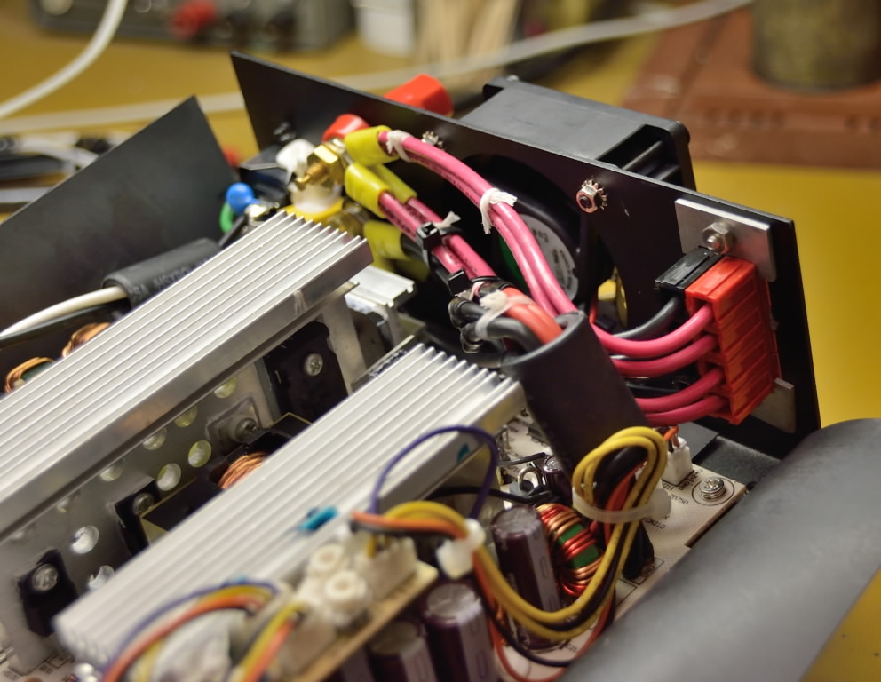
Finished
Options!
Powerpole mounting clip (pair) SKU: 1462G1
Powerpole Red and Black housings (PP15/30/45) and your choice of 30 or 45 Amp contacts.
#12 wire will fit into either. I used 30 Amp contacts.
Five way binding posts, Red/Black, 10-32 thread size
#12 wire, Red/Black
Ring Terminals, Yellow, Hole size 10, for 10-12 AWG wire
More Astron Power Supply Mods and Data can be found here