|
|
|
Introduction
Here is a simple circuit which is switchable between a sharp cut-off above 2.5 kHz and a narrow bandpass around 800 Hz. In the low pass (LP) state it can be used on speech as the filter section of a direct conversion receiver. For CW operation, the cut-off frequency is lowered to 800 Hz and another high pass (HP) section with cut-off below 800 Hz is added to form a narrow bandpass around 800 Hz. To use this. the CW Morse beat note is adjusted to the bandpass centre frequency.
Operation
In the following paragraphs operation of the circuit is described. If filter terminology used appears unfamiliar, the reader is referred to the opening paragraphs of the writer's previous article (reference 1). The article also discusses a little more about the types of filter employed here.
The circuit makes use of the National Semiconductor switched capacitor LP filter package type MF6. which includes two operational amplifiers with the sixth order Butterworth filter. The filter is also operated from its own internal clock operating at 50 times the cut-off frequency. To achieve the 2.5 kHz and 800 Hz LP cut-off, the clock frequency is switched between 125 kHz and 40 kHz respectively. As a sixth order Butterworth, the switched capacitor filter has an attenuation slope beyond cut-off of 36 dB per octave.
To produce the 800 Hz high pass, one of the operational amplifiers is connected as a second order Chebychev filter. This type filter gives a theoretical attenuation at the first octave of 17 dB, not as great as the LP filter but quite effective in reducing audio noise or interference below the 800 Hz centre frequency.
Figure 1 illustrates the filter system in block form. For speech, the LP filter is operated on its own. For CW its cut-off frequency is lowered and its output fed via the HP filter section.
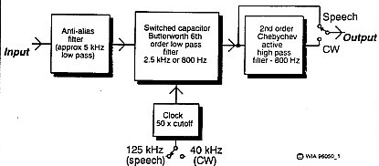
Switched capacitor filters produce spurious output signals if fed with a frequency close to their clock frequency. To guard against any such signal coming from the receiver, the switched capacitor filter is fed via a simple anti-alias filter with a roll-off above 5 kHz.
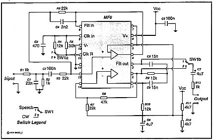
For circuit detail, refer to Figure 2. The MF6 package operates on a split power rail basis and a centre rail is derived from the single DC supply with resistors R11 and R12. Supply voltage is not critical and the circuit works on any well-filtered single DC supply between 8 and 14 volts.
The clock frequency is set by components C3, R4 and R5. Switch S1 selects speech or CW and its contacts S1a alter the resistance in the circuit to change the clock frequency and hence the LP cut-off frequency. Components C8, C9, R7, R8, R9 and R10 make up the HP Chebychev active filter in conjunction with one of the MF6 internal operational amplifiers. Switch contacts S1b connect the output either direct from the LP circuit or via the HP circuit.
The non-inverting input of the second operational amplifier is connected internally to centre rail, so this amplifier has had to be used in the inverting mode. Roll-over above 5 kHz for the anti-alias filter is partly done by capacitor C4 in the amplifier feedback circuit and partly by capacitor C1 at the input.
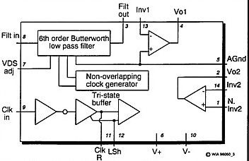
The internal functional block diagram for the MF6 is shown in Figure 3.
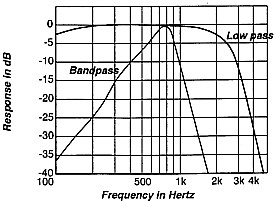
Performance
Measured response of the filter in its two
different modes is shown in Figure 4 at top of page.
Other relevant information is as follows:
Input Resistance - 2 kohms;
 Output Resistance - 1 kohm;
 Voltage Gain - LP = 0.5 and BP = 1.13;
 DC Supply Load Current - 5 mA (at 10 V) and
7 mA (at 12 V).
If required, the filter can be used as a stand-alone unit with its input fed from the output of a receiver or transceiver headphones jack. The output of the filter is suitable to operate into high impedance headphones. To operate a loudspeaker, a power amplifier such as the LM380 or LM386 can be added. Of course, the load current of these power amplifiers swings widely with variation in audio level and they require a well regulated power source, preferably isolated from the filter supply.
One characteristic of the switched capacitor filter is that there are output components near clock frequency. With the lowest cut-off at 800 Hz, these components are no lower in frequency than around 40 kHz and could easily be electrically filtered out. However, as they are outside the frequency range of the human ear, the car does the filtering for us.
Other Uses of the MF6
What's been described has been a circuit with fixed defined cut-off frequencies. However, the MF6 is very versatile because the LP cut-off can be set to any audio frequency by simply altering the circuit constants controlling the clock. It was used as a variable filter in a previous article (reference 1). In another article (reference 3), it was used in conjunction with a CMOS divider IC to make a Wideband Variable Audio Frequency Oscillator. If you interested in the switched capacitor filter, you might have a look at those applications.
Summary
A receiver audio filter has been described which makes use of a single MF6 switched capacitor filter package. It can be selected to operate either as a 2.5 kHz sharp cut-off low-pass filter for speech or a narrow bandpass filter around 800 Hz for keyed tone (as detected in CW mode). It could well be used as the audio filter in a direct conversion receiver where signal selectivity is achieved by the sharp cut-off response of the audio system.
References
1. Lloyd Butler VK5BR - An Adjustable Audio Filter System for the Receiver - Amateur Radio, March 1995.
2. MF6 6th Order Switched Capacitor Butterworth Lowpass Filter, National Semiconductor data sheets.
3. Lloyd Butler VK5BR - Wideband Variable Frequency Audio Oscillator - Amateur Radio, March 1988.