Sub Heading
By using the signals from two antennas, controlling their relative amplitudes and controlling the phase of one of them, unwanted signal or unwanted noise can be phased out. Circuitry is described which uses the signal from a wire antenna to provide selective cancelling against the signal output from an LF loop antenna.
Introduction
The fact that the phasing between a wanted signal and an unwanted signal can be different on different antennas is put to advantage. With this condition, the unwanted signal can be cancelled out by controlling amplitude and phase. The heart of the system is some form of phase control circuitry. I described methods for doing this at HF in AR Sept. 1992 (ref. 1) and AR Jan. 1993 (ref. 2). The second system made use of the 180 degree phase shift which was achieved when two lightly coupled tuned circuits were tuned from one side of resonance to the other by a ganged pair of variable capacitors. It is this system which is again used at LF.
The circuit described provides a phase and amplitude controlled auxiliary signal from a wire antenna. Whilst its output could be used to mix with some other antenna system, it was specifically aimed at mixing in with the signal from the loop antenna in the active loop converter described in AR Jul 2000 (ref. 3).
Circuit Detail
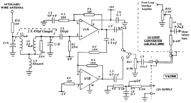
The circuit diagram is shown in figure 1. The auxiliary wire antenna is coupled into the phase control network L1-L2-L3-C1A-C1B via R10. The network is made up of two tuned circuits C1A-L1 and C1B-L2 coupled via inductor L3. The three inductors are miniature chokes obtainable from electronics stores. C1A and C1B with maximum capacities of 450pf are ganged. Using the component values shown, the circuit is tuneable over the range of 160 to 500 kHz. A phase control range of 180 degrees is achieved tuning from one side of resonance to the other with an amplitude variation not greater than 6db.
The phase control network is interfaced with amplifier V1A which is one half of an LM353 twin mosfet op. amp package. The circuit constants are set for a gain around 25. The other half, V1B, is connected as a phase inverter to provide the second half of the 360 degrees phase range. Switch S1 provides selection of one or the other ranges of 180 degrees.
The amplifiers operate from 12V DC picked up from the loop converter supply. Their operating points are set by 6V derived from R8 and R9.
The output from the auxiliary circuit is mixed in with the output from the loop converter interface amplifier at the NE602 mixer input, pin1. As there is a second input to the NE602 ( pin2), I could have fed the auxiliary signal via this second pin. However, I would have had to disconnect the converter circuit board card, remove it from its mounting and modify the board. I found it easier to add circuitry around the loop gain control RV2, as shown in the top right hand corner of figure 1, so that both signals are fed to pin 1.
There is nothing specific about requirements for the auxiliary antenna. The normal radio shack antenna used for HF communications can be connected for this purpose.
Operation
A little bit of practice is needed to set up the system on a station tuned in.
First of all set the auxiliary antenna gain control RV1 to zero and loop gain control RV2 in the converter well advanced or at maximum. Adjust the loop tuning for resonance indicated by maximum signal.
Now set the loop gain control RV2 to zero and advance the auxiliary gain control RV1. Adjust C1 in the phasing circuit for resonance indicated by maximum signal.
Restore loop gain control RV2 to its previous position so that signals from both antenna are feeding the mixer. Assuming there is unwanted noise or signal, carefully ‘fiddle’ with the tuning of C1 either side of resonance and the setting of auxiliary gain RV1 to find a null in the unwanted noise or signal. If there is no success, reverse phase with switch S1 and try again.
For the cancellation to work, the unwanted noise or signal from the auxiliary circuit must be at least equal in level to that from the loop circuit. If this is not the case, it might be necessary to reduce the loop level (RV2) to achieve this condition.
Performance
Whilst the main purpose in setting up the cancelling circuit was to phase out locally generated noise, it has also proved to be useful in separating signals. There are a multitude of aeronautical NDB signals to be heard above 200 kHz and many of these stations are on the same frequency or very close in frequency. Tune across the band and at many tuned positions more than one station ident. can be heard.
Assuming the signals are from different directions, one way to separate one station from another is to carefully set the loop null in the direction of the signal to be rejected. However, independent of the loop position, the cancelling circuit is also very effective in phasing out the unwanted signal. It is interesting to phase out one or the other of two signals so that each can be heard on its own, one at a time.
If there is no signal or noise to be cancelled, another interesting aspect of having two different types of antenna is that either can be selected to operate in its own right. If the signal from the loop seems better than that from the wire antenna , just set RV1 to shut off the auxiliary signal. If the signal from the wire antenna seems better, set RV2 to shut off the loop. In the presence of local noise, the loop is normally much better. However if the general band noise is very low and comparable with the noise generated by the loop and its pre-amplifier, then a long wire and its higher level of signal pick-up can produce higher signal to noise ratio.
Summary
The LF Noise & Signalling Cancelling circuit is a useful addition to the LF receiving system where localised noise is a problem. It is also useful to phase out an unwanted signal near the frequency of the signal being received.
As described, the circuit has been designed to operate in
conjunction with the LF Active Loop Converter described in AR, July
2000. In the combined arrangement, the following is achieved:
The advantage of the loop with its properties of directivity and insensitivity to the high level electric component of localised noise.
The ability to raise the Q of the loop by feedback and limit its bandwidth.
The ability to phase out unwanted noise or signal by using an additional antenna pick-up.
The ability to select loop or wire antennas for best signal condition.
Using components shown in figure 1, the phase control circuit works over the frequency range of 160 to 500 kHz. No attempt has been made to operate below 160 kHz but this might be achieved by using large values of inductance in the circuit.
References
1. An Interference Cancelling System for your Receiver or Transceiver - Lloyd Butler VK5BR - Amateur Radio, September 1992.
2. More on- Interference Cancelling and a New Circuit - Lloyd Butler VK5BR - Amateur Radio, January 1993.
3. An Active Loop Converter for the LF Bands - Lloyd Butler VK5BR - Amateur Radio, July 2000