 |
Uses a Single Active CMOS Package |
Forward
The receiver design came about because the Adelaide Hills Amateur Radio Society (AHARS) were to hold a One Active Device competition in August 1999 and members, including myself, constructed entries in anticipation of the competition meeting. The rules were a single active device (i.e. a single valve, transistor, or integrated circuit package) and it must have some use in Amateur Radio. Diodes or other non amplifying devices were considered as passive and could be included.
Whilst I was unable to attend the Competition Meeting, I did prepare the receiver entry which is described here. In my folly, I set out to build a complete receiver using a HEF4069UB hex inverter. My article describes the receiver together with some troubles I had on my way in making it work.
The 4069 package consists of six separate unbuffered stages each consisting of a complimentary symmetry MOSFET pair (CMOS). Because the stages are unbuffered, they can be used in a linear amplification mode with their operating point centred by simply connecting a resistor directly between output and input.
First of all I must say that in all sanity, using a number of individual stages in this package all tuned to the same frequency is hardly the ideal way to go about designing a receiver. Because of the common rail supply within the package, there is no way that the individual supplies to stages can be de-coupled from each other. Added to that, the individual stage components have to be clustered around the DIL package like sardines in a can and there is a problem of output to input capacitive coupling within the package itself. Needless to say, I had my troubles controlling interaction between the individual stages. However the adjudicators of this excercise had ruled "one active device meaning one valve, transistor or integrated circuit unit" so one package it is. They also decreed that it should be something used in the Ham shack, hence the tuning range includes 1.8 MHz.
|
Uses a Single Active CMOS Package |
The Circuit
My first operation was to check out individual circuit section design starting with the audio section. Two inverter stages of the I/C are used in what I will call a psuedo push pull arrangement to provide twice the power output of one stage. I will call it psuedo because the input of one stage is derived from the output of the other and therefore the arrangement does not have the even harmonic cancelling characteristic of a true push pull stage. (The fact is that with only six inverter stages in the package, I could not afford to use another one to provide phase inversion for true push pull).
The audio stage supplies around 5 milliwatts of output power. I selected the most suitable output transformer I could find in the Junk box and a fairly sensitive speaker. Despite the low power, it provides quite a surprising level of sound, quite adequate for comfortable listening.
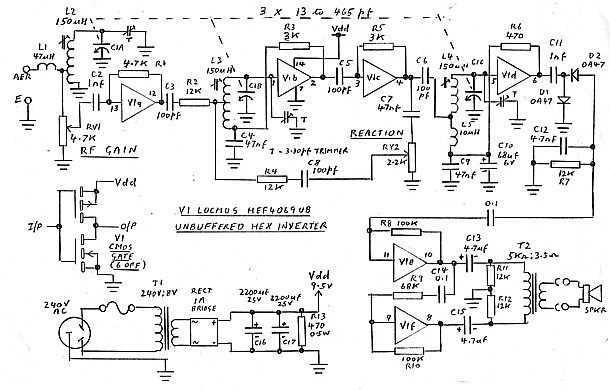
The audio stage is included in the overall diagram, figure 1. Note that V1f requires a gain of -1 and as the open loop gain is not particularly high, R9 is selected lower than R10 to achieve this. Also note that resistors R11 and R12 are there simply to polarise electrolytic capacitors C13 & C15 in the absence of a centre tap in T2.
The next operation was to check out a single RF stage and ultimately three of these (V1b, V1c and V1d) were wired in on an experimental card with the audio section and a front end buffer stage (V1a). The three stages were tuned with the 3 gang tuning capacitor (Cl). The result was a disaster as I was unable to stop instability caused by interstage coupling.
So I deleted the the tuned circuit at the front of V1c and rewired the V1c circuit as the buffer as shown to provide a degree of isolation between stages V1b and V1c. This now worked fine with two tuned RF circuits instead of three. However there did seem to be a need for selective tuning at the front to improve the adjacent channel rejection and improve cross modulation performance in the presence of strong broadcast station signals on the band. One section of the tuning gang was now spare and I used this in conjunction with L2 mounted on a separate card to provide a front end pre-selection circuit.
The receiver is not all that sensitive and needs a fair length of aerial wire for operation. Using a long wire, I had some trouble with tuned circuit tracking at the high frequency end of the tuning range due to aerial capacitance detuning C1A-L2 circuit. To offset this problem to some effect, inductor L1 has been connected in series with the aerial.
Regeneration from the output of P1c into tuned circuit L3-C1B has been included to raise the effective Q of that circuit and improve the gain and selectivity of the receiver. For best performance, reaction control RV2 is adjusted to a point just below circuit oscillation.
I originally intended that the receiver be operated from a 9V battery. However the receiver needs an earth connected as well as an aerial wire and a mains sourced power supply was fitted to ensure that an RF earth was provided from that source when the time came to demonstrate the receiver. Note that there is no voltage regulator in the power supply as this would have constituted another active device and broken the rules.
Minimum discernible signal level is around 10 microvolts at the high frequency end of the tuning range and about 30 microvolts at the low frequency end. As such, the receiver requires sufficient length of aerial to enable signal pick-up above these levels. Rf gain control (RV1) at V1a input must be set to prevent overload on strong signals. It is also used to control the audio output level from the loudspeaker. (I originally had an additional audio gain control at the output of the detector stage D1-D2 but as maximum output power was limited by RF overload rather than audio overload, I decided the audio gain control was superfluous).
As an alternative to using the aerial wire, I have operated the receiver on a 0.8 metre diameter tuned loop which I sometimes use on 1.8MHz. This works very well but I could not use it in the competition as the loop circuit includes a FET interface amplifier, constituting a forbidden extra active device. I have also tried a ferrite rod loop antenna but signal pick-up from this proved to be inadequate.
In Conclusion
So a single active device was developed with three tuned RF stages to satisfy the rules of the competition and tunes the MF Broadcast Band and the 1.8 MHz Amateur Band. It is not particularly sensitive and does require a good aerial. However, it does work and it does provide an interesting example of how unbuffered CMOS inverters, such as the 4069 and 74C04, can be used for linear amplification applications.