Bench Power Supply
I have been using a form of this power supply for decades. My original version was continuously variable 0 to 25 volts and had analog volts and amps meters. The ammeter had a range switch, which always caused problems due to poor contacts; on the amps setting the switch resistance was too erratic. (I should say that I was using a surplus switch from ages ago, I could have bought a new switch that would have worked better. But trying to shunt a 100uA meter with a tiny resistance through a switch contact is looking for trouble.)
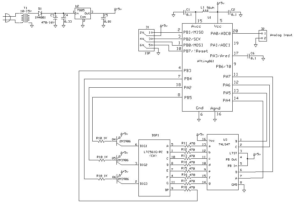
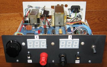
One day I decided to build a new version of the supply using digital displays. Since 3 digits were sufficient for amps and volts, I chose an LED display. It would be easy to use an LCD display too. The voltmeter reads 0.0 to 99.9, and the ammeter is autoranging 0 to 999 mA then n.nn amps.
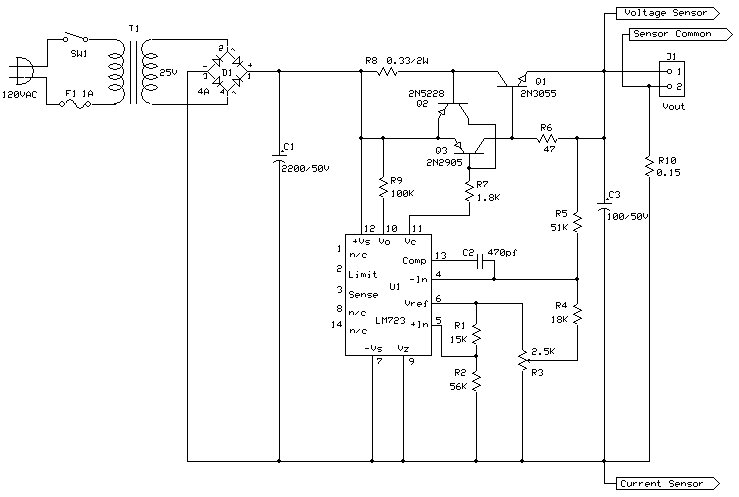
The best feature of this supply is that the voltage is continuously variable from zero to maximum using a potentiometer. I'd like to take credit for this circuit, but I found it in an issue of Electronics Designer's Casebook from the around the 1970s.
The power supply is pretty much out of the casebook, except for the addition of a 0.15 ohm 5 watt resistor, R10. This develops a voltage for the ammeter.
The maximum voltage of this supply depends on T1. You can choose it to produce more voltage but several components must be chosen to suit, and the voltmeter interfaced properly. You can get around 2 amps from this supply, more if you work out the design details.
There are two ATtiny861 measurment circuits, one for volts and one for amps. I used a separate power supply for each one, to allow for power supply isolation. I used a separate transformer with two secondaries for the two supplies. I found that when sharing the power supply, the ammeter had a lot of jitter which was only cured by giving it its own supply. The schematic does not show a voltage divider required on the analog input of the voltmeter, to limit the voltage presented to 5 or less. The ratio will depend on the maximum voltage of your supply. Once built you will have to customize the code a bit to match your circumstances. However it is all WinAVR code, the compiler is free.
Download C source code for LED Voltmeter