Clock with Nokia 5110 LCD Display
Another clock? I didn't really need another clock,
but this project nevertheless has its compelling features. First,
I stumbled across a very interesting LCD display, the Nokia 5110. I
also found a cheap Chinese pushbutton rotary encoder, very similar to
the CTS encoder I had used before. I wanted to give these
gadgets a try. To make the project more interesting I decided to do it
with no RTC clock chip.
The Nokia 5110 is a 48 x 84 pixel graphic display.
This
makes it feasable to use a small font for programming menus, and a
large font for the time display. Support code was available on the
vendor's web site, which saved me a lot of development time. The
display is rated for 2.7 to 3.3 volts, so I chose to power the project
with a 3.3V regulator and 3V backup battery.
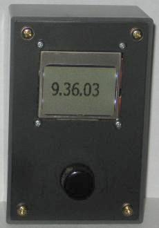
Its hard to see in the photo, but there's a pushbutton
rotary encoder below the display. It is a model EC11-1B-18T
made by
Changzhou Xinze Electronic Co. It is very similar mechanically and
electrically to the CTS series 290 rotary
encoder I used before. As a bonus it is easy to panel mount, and seems to
work quite well.
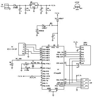
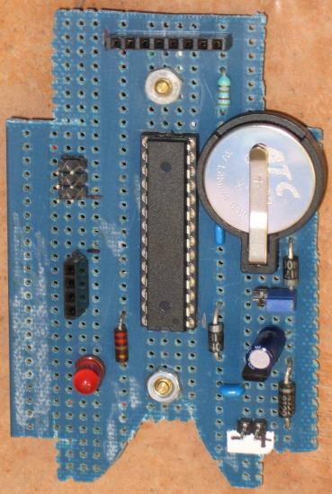
I chose an ATmega88PA for this project.
It is a good match for the number of IOs required, and flash memory
size. Also the chip is a picopower chip, which seemed to be a good
idea
since this project must draw minimal power when offline. A tiny 32.768
KHz watch crystal is connected to TOSC1 and TOSC2. This provides
clocking for timer/counter 2. Divided properly, the result is an
interrupt every second, great for running a clock.
When the
clock is unplugged or power fails, the time must be maintained in the
processor. This means a backup battery, and power consumption must be
kept to a minimum. In asynchronous mode timer/counter 2 keeps running
even when the
processor is placed in power-saving sleep. Each second an
interrupt wakes up the processor so that the clock can be updated,
then
sleep is resumed. The result is a drop in power consumption from 3 to
4
mA when powered up to 3 uA when powered from the battery.
PD2/INT0
is tied to the power supply. It is programmed to produce an interrupt
whenever there is a level change. This lets the program know when power
goes up and down. When power goes down, the LCD is powered off and
power saving sleep mode entered. When power comes back on, normal
operation is resumed.
If you are puzzled by some of the code to do with sleep mode, have a look
at AVR134 Real-Time Clock using
the Asynchronous Timer (PDF,
sample code).
There
are a few tweaks in the code that are not obvious, but shown in
the application note. Believe me if you omit anything sleep mode will
not work as expected.
Programming
the clock is simple. Press the
encoder button and programming mode is entered. A series of menus are
shown to get the 12/24 hour format, the hours, minutes and seconds. A
final press of the button returns to normal time display. One nice
thing, you don't have to wait until the seconds become zero to set the
clock, like you do with a RTC chip. Spin the rotary to any appropriate
seconds value, and when the seconds match, press the button and the
time is set.
The
value of C1 and C2 depend on the rated load capacitance of the watch
crystal you use. Unfortunately I used one from my partsbin and I didn't
know what the rated capacitance was. I started with large capacitors
and found the clock ran too slow. I gradually reduced the capacitors
until the clock ran correctly. A tiny variable trimmer is useful for
getting the clock right on time. I ended up with 2 to 4 pF on each leg
of the crystal, so the crystal was probably a 6 pF load type.
The fuses are programmed for an internal RC oscillator @ 8 MHz with 65ms
delay.
Download C
source
code for the clock
Back
to VE3LNY's AVR Project Page
