PIC Cable Tester
I discovered a project here
for a network cable tester. It uses a few CMOS chips and a lot of LEDs
and can identify common ethernet cables (patch, cross). I was just
about to build it when I thought, why not do it with a microprocessor?
Of course it is more complicated, but also more flexible. The cable
type can be identified in the software, so extra connectors are not
required. Better still, any cable with 1 to 8 conductors can be tested,
making the unit more useful. I selected a big 40-pin microprocessor,
the PIC16F877A, although the project would still fit in a PIC16F874A.
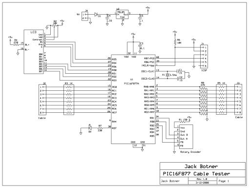
Pins RC0 through RC7 are defined as output pins and drive the
cable under test. The other end of the cable is connected to pins
RA0..RA3, RA5, and RE0..RE2, defined as inputs. I chose those pins
because they correspond to AN0..AN7, and early on I thought that it
might be possible to measure the resistance of the conductors somehow.
For the sake of simplicity I gave up on that idea. The R3 and R5
resistor networks are for protection of the input and output ports. I
thought about using diodes on the input side as well but ran out of
room on my project board. The R8 resistor network makes sure the input
pins sit at ground when not otherwise connected.
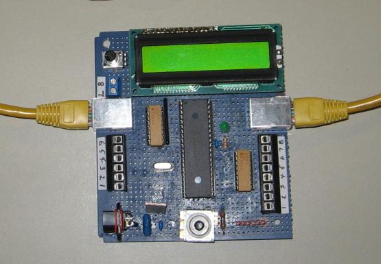
A standard 2X16 LCD module is used to display information. For input
I use a rotary encoder with inegrated pushbutton, the Grayhill
62P22-L4, available from DigiKey as part
number GH7295-ND
(now obsolete). (More information on this part can be found
on my rotary encoder page.)
There is a LED on port RD7 which flashes on and off once a second,
which you can leave out if you like. I used a 3.54 MHz crystal from my
junkbox, but almost any clock frequency will work. I programmed the PIC
using my PICkit
2 and the ICSP header.
The
cable connects to two RJ45 sockets at J2 and J3. In addition, I placed
screw-on terminals so that other cables can be tested.
The
really interesting part of this project is the software. The rotary
encoder debouncing and decoding routines are in a separate module,
encoder.c. The rest of the code is in the main module. Timer1 is used
to generate 4 ms interrupts for debouncing the encoder. The mainline
runs through 4 steps. The 1st step prompts you to enter the number of
conductors in the cable under test, which you do by turning the
encoder. When ready, press the button, and step 2 runs a test on the
cable. An array of 8 bytes is used to map the cable connections. Each
byte in the array corresponds to one conductor, and each bit in a byte
corresponds to a conductor that it maps to. So for example, if
conductor 1 on one end of the cable connects to conductor 1 at the
other end, the 1st byte in the array is x'01'. If conductor 1 connects
to pin 8 at the other end, the byte would be x'80'. Each conductor is
activated in turn and the responses mapped at the other end.
Once
the cable has been analyzed, step 3 produces a report. The connections
of 2 conductors are displayed on the lcd. If there are more than 2
conductors, rotate the encoder to see the rest of the conductors, and
the list scrolls down or up. When done, press the button. The last step
only occurs when a recognized network cable is detected. The type of
cable (patch, cross, etc.) is displayed on the lcd. Press the button
again and you return to step 1.
If you work with particular
kinds of cables, you can easily adapt the hardware and software to
recognize those cables. Add connectors for your favorite cables to the
inputs and outputs, and customize the report code in step 4.
Download C
source code for the Cable Tester (
SourceBoost
BoostC)
Update (02/2009) I discovered an article in July 2006 QST
magazine, "A CAT5 Cable and Connector Tester" by K8AXW which describes
a simple CAT5 cable tester. This was followed up in Jan. 2007 QST
Technical Correspondence "Comments on the CAT5 Cable and
Connector Tester" by W0ZW, which describes why simple continuity
testing on a CAT5 cable is not sufficient. He says, "It is possible for
a cable to test good yet in fact be faulty". The problem is that DC
continuity testing does not ensure improper pairing of the twisted
pairs. When this happens, crosstalk is not reduced as intended, and the
cable can fail to work, or work erratically. Of course, my cable tester
does not test for proper pairing either.
Back
to VE3LNY's PIC Project Page
